Capacitors, essential components in electronic circuits, can be connected in series or parallel configurations to achieve specific electrical characteristics. Understanding the differences between these two configurations is crucial for designing and troubleshooting electronic circuits.
In this blog post, we’ll delve into the key distinctions between capacitors in series and parallel, exploring their behavior, applications, and implications for circuit design.
What Are Capacitors in Series

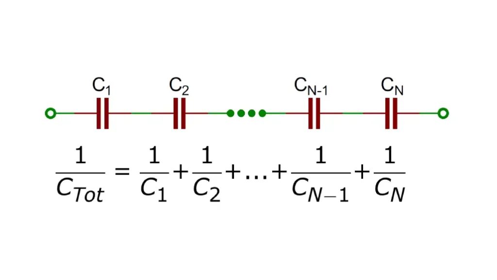
When capacitors are connected in series, their total capacitance decreases. This is because the effective plate separation increases, which reduces the overall capacitance.
Key points to remember:
- Same Charge: All capacitors in series share the same charge.
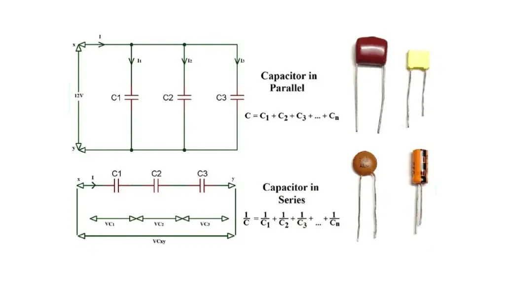
- Total Capacitance: The reciprocal of the total capacitance is equal to the sum of the reciprocals of the individual capacitances:
1/C_total = 1/C1 + 1/C2 + 1/C3 + ... - Voltage Division: The voltage across each capacitor is inversely proportional to its capacitance. This means that larger capacitors will have a smaller voltage drop across them, and smaller capacitors will have a larger voltage drop.
Example:
If you have three capacitors with capacitances of 2F, 3F, and 5F connected in series to a 12V battery, the total capacitance will be:
Capacitor in series formula:
1/C_total = 1/2F + 1/3F + 1/5F
Solving for C_total, you’ll find that the total capacitance is less than the smallest individual capacitance.
Important Consideration:
When connecting capacitors in series, it’s crucial to consider their voltage ratings. The voltage across each capacitor will depend on its capacitance relative to the others. The maximum voltage rating of the series combination is equal to the sum of the voltage ratings of the individual capacitors.
By understanding these concepts, you can effectively design circuits that utilize capacitors in series to achieve specific capacitance and voltage requirements.
What Are Capacitors in Parallel

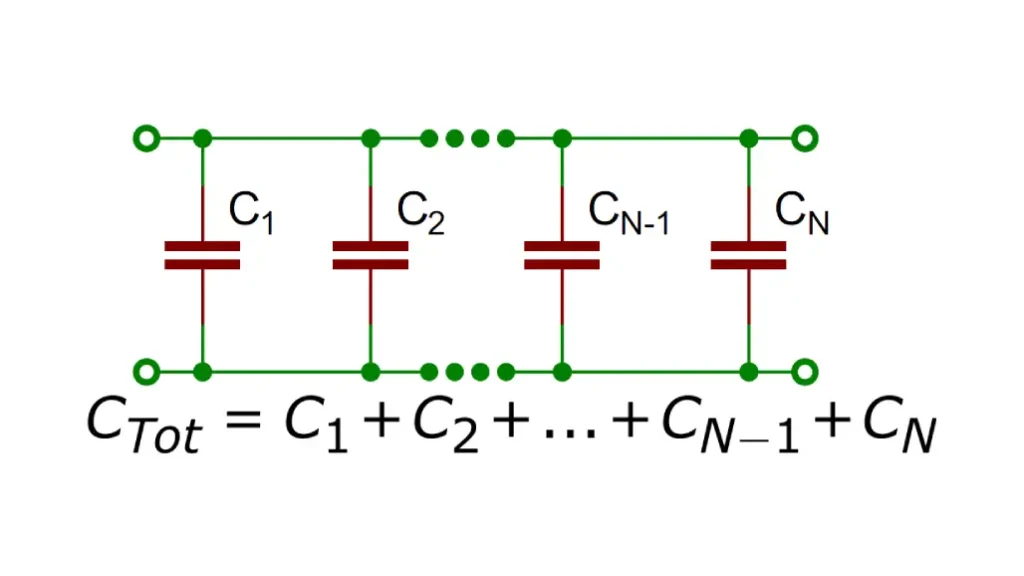
When capacitors are connected in parallel, they effectively increase the total plate area available for storing charge. This results in an increase in the total capacitance of the circuit.
Key points to remember:
- Same Voltage: All capacitors in parallel have the same voltage across their plates.
- Total Capacitance: The total capacitance of the parallel combination is the sum of the individual capacitances:
C_total = C1 + C2 + C3 + ...
Example:
If you have three capacitors with capacitances of 2F, 3F, and 5F connected in parallel to a 12V battery, the voltage across each capacitor will be 12V. The total capacitance of the combination will be:
capacitors in parallel formula:
C_total = 2F + 3F + 5F = 10F
Important Consideration:
When connecting capacitors in parallel, it’s crucial to consider their voltage ratings. The maximum voltage rating of the parallel combination is equal to the lowest voltage rating of any individual capacitor.
For instance, if you have a 100V capacitor and a 50V capacitor in parallel, the maximum voltage you can apply to the combination is 50V, as exceeding this voltage could damage the 50V capacitor.
Capacitors in Series vs Parallel

Capacitors, like resistors, can be connected in series or parallel to achieve specific capacitance values and voltage ratings.
Capacitors in Series
- Same Charge: All capacitors in series share the same charge.
- Voltage Division: The voltage across each capacitor is inversely proportional to its capacitance.
- Total Capacitance: The reciprocal of the total capacitance is the sum of the reciprocals of the individual capacitances:
1/C_total = 1/C1 + 1/C2 + 1/C3 + ...
Key point: The total capacitance of capacitors in series is less than the smallest individual capacitance.
Capacitors in Parallel
- Same Voltage: All capacitors in parallel have the same voltage across their plates.
- Total Capacitance: The total capacitance is the sum of the individual capacitances:
C_total = C1 + C2 + C3 + ...
Key point: The total capacitance of capacitors in parallel is greater than the largest individual capacitance.
Choosing the Right Configuration:
The choice between series and parallel connections depends on the specific requirements of the circuit.
- Series Connection: Used to increase the voltage rating of a circuit or to obtain a specific capacitance value that is smaller than any individual capacitor.
- Parallel Connection: Used to increase the total capacitance of a circuit or to increase the amount of energy that can be stored.
By understanding the behavior of capacitors in series and parallel, you can effectively design circuits to meet specific electrical needs.
Capacitors in series vs parallel comparison chart
| Feature | Series Connection | Parallel Connection |
|---|---|---|
| Voltage | Voltage is divided across the capacitors | Voltage is the same across all capacitors |
| Charge | Same charge on each capacitor | Different charges on each capacitor |
| Total Capacitance | 1/C_total = 1/C1 + 1/C2 + … | C_total = C1 + C2 + C3 + … |
| Application | Increasing voltage rating, decreasing capacitance | Increasing capacitance, maintaining voltage rating |
Is It Better to Put Capacitors in Series or Parallel
Whether it’s better to put capacitors in series or parallel depends on your specific circuit design goals.
Series Connection:
- Increases voltage rating: This is useful when you need a capacitor to withstand a higher voltage than any single capacitor can handle.
- Decreases capacitance: This can be useful in certain filter circuits or timing circuits where a lower capacitance is required.
Parallel Connection:
- Increases capacitance: This is useful when you need a higher capacitance to store more energy or to filter lower frequencies.
- Maintains voltage rating: The voltage rating of the parallel combination is the same as the lowest voltage rating of any individual capacitor.
Consider the following factors when deciding:
- Required capacitance: Do you need a higher or lower capacitance?
- Required voltage rating: Do you need a higher voltage rating than any single capacitor can handle?
- Physical size and weight: Parallel connections can be more compact, while series connections can be bulkier.
- Cost: The cost of capacitors can vary, so consider the total cost of the components.
Ultimately, the best configuration depends on the specific needs of your circuit. By understanding the characteristics of series and parallel connections, you can make informed decisions to optimize your design.
Need help with your capacitor selection? Contact us today for a quote on high-quality capacitors tailored to your specific needs.
How to Tell if a Capacitor is in Series or Parallel
To determine if capacitors are connected in series or parallel, you can follow these guidelines:
Series Connection:
- One Path: There is only one path for current to flow through all the capacitors.
- Same Charge: All capacitors in series have the same charge.
- Voltage Division: The voltage is divided among the capacitors based on their capacitance.
Parallel Connection:
- Multiple Paths: There are multiple paths for current to flow, with each capacitor having its own branch.
- Same Voltage: All capacitors in parallel have the same voltage across them.
- Current Division: The current is divided among the capacitors based on their capacitance.
Visual Inspection:
- Series: Capacitors are connected end-to-end, like a chain.
- Parallel: Capacitors are connected side-by-side, with both positive terminals connected together and both negative terminals connected together.
Remember:
- Series: Total capacitance decreases.
- Parallel: Total capacitance increases.
By understanding these characteristics, you can easily identify the configuration of capacitors in a circuit.
Is the Voltage the Same in Series or Parallel Capacitors
The voltage across capacitors depends on whether they are connected in series or parallel:
Series Connection:
- Different Voltages: The voltage is divided among the capacitors.
- Larger Capacitor, Smaller Voltage Drop: Capacitors with larger capacitance will have a smaller voltage drop across them.
- Smaller Capacitor, Larger Voltage Drop: Capacitors with smaller capacitance will have a larger voltage drop across them.
Parallel Connection:
- Same Voltage: All capacitors in parallel have the same voltage across them.
- Equal Voltage: The voltage across each capacitor is equal to the voltage of the source.
In summary:
- Series: Different voltages across each capacitor.
- Parallel: Same voltage across all capacitors.
How to Calculate Capacitor in Series and Parallel
Calculating Capacitors in Series
When capacitors are connected in series, the reciprocal of the total capacitance is equal to the sum of the reciprocals of1 the individual capacitances:
1/C_total = 1/C1 + 1/C2 + 1/C3 + ...
Calculating Capacitors in Parallel
When capacitors are connected in parallel, the total capacitance is simply the sum of the individual capacitances:4
C_total = C1 + C25 + C3 + ...
Example:
Let’s say we have three capacitors with capacitances of 2F, 3F, and 5F.
Series Connection:
1/C_total = 1/2F + 1/3F + 1/5F
Solving for C_total, you’ll find that the total capacitance is approximately 0.97F.
Parallel Connection:
C_total = 2F + 3F + 5F = 10F
Remember:
- Series: Total capacitance decreases.
- Parallel: Total capacitance increases.
By understanding these formulas, you can easily calculate the total capacitance of any combination of capacitors in series and parallel.
Conclusion
In conclusion, understanding the differences between series and parallel capacitor configurations is crucial for optimizing circuit design and performance. By carefully considering factors like total capacitance, voltage rating, and energy storage, you can select the appropriate configuration for your specific application.
Need high-quality capacitors for your next project?
Contact us today to get a quote on our wide range of capacitors. Our team of experts can help you select the right components for your specific needs.