Capacitors are integral components in electronic circuits, storing and releasing electrical energy as needed. Understanding how capacitors behave in series connections is crucial for designing and troubleshooting circuits effectively.
In this comprehensive guide, we will explore the basics of capacitors in series, from their fundamental principles to practical applications.
What Are Capacitors
Capacitors are passive electronic components that store electrical energy in an electric field. They consist of two conductive plates separated by an insulating material, known as a dielectric. When a voltage is applied across the plates, charge accumulates, creating an electric field between them.
Types of Capacitors
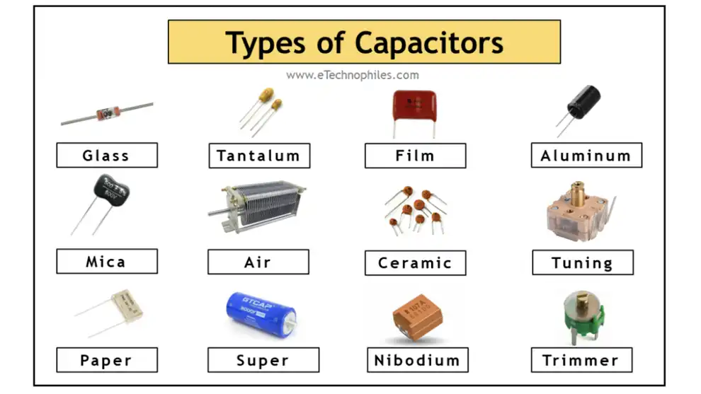
Capacitors come in various types, each tailored for specific applications in electronic circuits. Understanding the different types can help you choose the right capacitor for your project. Let’s explore some common types:
1. Ceramic Capacitors
Ceramic capacitors are widely used for their small size, high capacitance values, and low cost. They are versatile and suitable for applications requiring stable capacitance over a wide temperature range.
2. Electrolytic Capacitors
Electrolytic capacitors are polarized and typically offer higher capacitance values than ceramic capacitors. They are commonly used in power supply circuits and audio applications due to their high capacitance and low cost.
3. Tantalum Capacitors
Tantalum capacitors are known for their high capacitance density and low leakage current. They are suitable for applications where space is limited and reliability is crucial, such as mobile devices and medical equipment.
4. Film Capacitors
Film capacitors are known for their excellent temperature stability and high voltage ratings. They come in various dielectric materials, including polyester, polypropylene, and polycarbonate, offering versatility for different applications.
5. Aluminum Capacitors
Aluminum capacitors are similar to electrolytic capacitors but use aluminum as the electrode material. They offer high capacitance values and are commonly used in audio circuits and power supply filtering.
6. Supercapacitors
Supercapacitors, also known as ultracapacitors, offer high energy storage capacity and rapid charge-discharge cycles. They find applications in energy harvesting, regenerative braking systems, and backup power supplies.
7. Variable Capacitors
Variable capacitors have adjustable capacitance values, allowing for precise tuning in radio frequency (RF) circuits and oscillators. They consist of two or more plates separated by air or a dielectric material, with a movable rotor to change the capacitance.
Capacitors in Series
Capacitors in series refer to the arrangement of multiple capacitors connected end-to-end within an electrical circuit. This configuration alters the total capacitance and voltage handling capabilities of the circuit. Let’s explore the concept further:
Definition and Purpose
Capacitors in series are connected sequentially, forming a chain-like structure within the circuit. This arrangement serves various purposes, including voltage division, energy storage, and filtering in electronic circuits.
Total Capacitance in Series
The total capacitance of capacitors in series differs from that of capacitors in parallel. In series connections, the total capacitance decreases compared to individual capacitors. This decrease is due to the reciprocal relationship between capacitances in series.
Voltage Distribution
When capacitors are connected in series, the applied voltage divides across them based on their capacitance values. Capacitors with higher capacitance experience lower voltage drops, while those with lower capacitance bear higher voltages.
Applications and Circuit Design
Series-connected capacitors find applications in various circuit designs, including voltage dividers, signal filtering, and energy storage circuits. Understanding their behavior is crucial for designing circuits with specific voltage requirements and frequency responses.
Implications of Series Connection
Connecting capacitors in series alters the overall behavior of the circuit, affecting parameters such as capacitance, voltage handling, and energy storage. Engineers must consider these implications when designing circuits to ensure optimal performance.
Practical Examples
For example, in a voltage divider circuit, series-connected capacitors can be strategically chosen to regulate output voltages effectively. By selecting appropriate capacitor values, engineers can design circuits that meet voltage regulation requirements.
Challenges and Solutions
Series connection introduces challenges such as voltage imbalance and tolerance issues. However, careful circuit design and component selection can mitigate these challenges, ensuring reliable operation.
Capacitors in Series and Parallel
Capacitors can be connected in circuits either in series or in parallel configurations, each offering distinct advantages and applications. Let’s explore the differences and implications of capacitors in series and parallel:
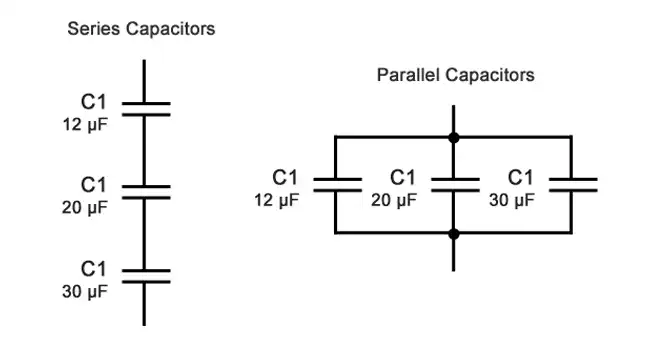
Series Connection
In a series connection, capacitors are linked end-to-end within the circuit, forming a chain-like structure. This arrangement alters the total capacitance and voltage handling capabilities of the circuit. The total capacitance in series decreases compared to individual capacitors, calculated using the reciprocal relationship between capacitances.
Parallel Connection
In contrast, parallel connection involves connecting capacitors side by side, with all their positive terminals connected together and all negative terminals connected together. This configuration increases the total capacitance of the circuit compared to individual capacitors. The total capacitance in parallel is the sum of the individual capacitances.
Implications and Applications
Series-connected capacitors find applications in voltage dividers, signal filtering, and energy storage circuits. They are suitable for scenarios requiring precise voltage distribution and regulation. Parallel-connected capacitors, on the other hand, are used in applications where increased capacitance is desired, such as smoothing power supplies and decoupling noise in circuits.
Total Capacitance and Voltage Distribution
In series connection, the total capacitance decreases, and the applied voltage divides across capacitors based on their capacitance values. In parallel connection, the total capacitance increases, and each capacitor shares the applied voltage equally.
Practical Considerations
When designing circuits, engineers must consider factors such as voltage rating, capacitance values, and tolerance to ensure proper operation. Additionally, understanding the implications of series and parallel connections is crucial for optimizing circuit performance and reliability.
Capacitors can be connected in circuits either in series or in parallel configurations, each offering distinct advantages and applications. Let’s explore the differences and implications of capacitors in series and parallel:
| Aspect | Series Connection | Parallel Connection |
|---|---|---|
| Arrangement | Capacitors are connected end-to-end, forming a chain-like structure. | Capacitors are connected side by side, with all positive terminals connected together and all negative terminals connected together. |
| Total Capacitance | Total capacitance decreases compared to individual capacitors. | Total capacitance increases compared to individual capacitors. |
| Voltage Handling | Applied voltage divides across capacitors based on their capacitance values. | Each capacitor shares the applied voltage equally. |
| Implications | Suitable for precise voltage distribution and regulation. | Suitable for applications requiring increased capacitance. |
| Applications | Voltage dividers, signal filtering, and energy storage circuits. | Smoothing power supplies, decoupling noise in circuits. |
Practical Considerations
When designing circuits, engineers must consider factors such as voltage rating, capacitance values, and tolerance to ensure proper operation.
Additionally, understanding the implications of series and parallel connections is crucial for optimizing circuit performance and reliability.
Capacitors in Series Formula
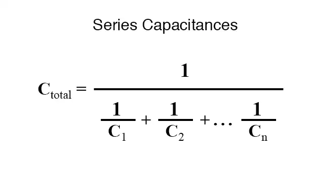
The formula to calculate the total capacitance (C_total) when capacitors are connected in series is:
𝐶total=11𝐶1+1𝐶2+…+1𝐶𝑛Ctotal=C11+C21+…+Cn11
Where:
- 𝐶totalCtotal is the total capacitance of the series connection.
- 𝐶1,𝐶2,…,𝐶𝑛C1,C2,…,Cn are the capacitance values of each individual capacitor connected in series.
This formula represents the reciprocal sum of the individual capacitances, providing the total capacitance of the series connection.
Here is a formula of capacitor in series:
Capacitors in Series Formula
The formula to calculate the total capacitance (C_total) when capacitors are connected in series is:
C_total = 1 / (1/C1 + 1/C2 + ... + 1/Cn)
Where:
C_totalis the total capacitance of the series connection.C1, C2, ..., Cnare the capacitance values of each individual capacitor connected in series.
This formula represents the reciprocal sum of the individual capacitances, providing the total capacitance of the series connection.
Capacitors in Series Calculator
Calculate the total capacitance when capacitors are connected in series.
Input:
- Enter the capacitance values of each capacitor (in Farads):
- Capacitor 1 (C1):
- Capacitor 2 (C2):
- Capacitor 3 (C3):
- …
- Capacitor n (Cn):
Output:
- Total Capacitance (C_total) in series:
Calculation Formula:
Total Capacitance (C_total) = 1 / (1/C1 + 1/C2 + … + 1/Cn)
Example:
- Capacitor 1 (C1) = 10 μF
- Capacitor 2 (C2) = 20 μF
- Capacitor 3 (C3) = 30 μF
Total Capacitance (C_total) = 1 / (1/10μF + 1/20μF + 1/30μF)
Total Capacitance (C_total) ≈ 5.4545 μF
Capacitors in Series Calculator
Do Capacitors in Series Have the Same Voltage
In a series connection of capacitors, each capacitor shares the same amount of charge, but they may not necessarily have the same voltage across them. The voltage across each capacitor depends on its capacitance value relative to the total capacitance of the series connection and the applied voltage.
According to Kirchhoff's voltage law, the sum of the voltages across all components in a series circuit must equal the total applied voltage. Therefore, the voltage across each capacitor in a series connection will be proportional to its capacitance value compared to the total capacitance of the series connection.
In practical terms, capacitors in series with higher capacitance values will have lower voltages across them, while capacitors with lower capacitance values will have higher voltages across them. This distribution of voltage ensures that the sum of the voltages across all capacitors equals the total applied voltage in the series circuit.
So, while capacitors in series share the same charge, they may have different voltages across them based on their individual capacitance values and their arrangement within the series connection.
How to Tell if Capacitors Are in Series or Parallel
Determining whether capacitors are connected in series or parallel in a circuit requires careful examination of their physical arrangement and electrical connections. Here are some steps to help you differentiate between series and parallel connections of capacitors:
Series Connection:
- Physical Arrangement: Check if the capacitors are connected end-to-end, forming a chain-like structure within the circuit.
- Electrical Connections:
- Ensure that one terminal of each capacitor is connected to the next capacitor in the chain, forming a continuous path for current flow.
- Confirm that all capacitors share the same current path without branching off.
- Voltage Drop: Measure the voltage across each capacitor. In a series connection, the voltage across each capacitor will add up to the total applied voltage.
Parallel Connection:
- Physical Arrangement: Look for capacitors connected side by side, with all their positive terminals connected together and all negative terminals connected together.
- Electrical Connections:
- Check if all positive terminals of the capacitors are connected to a common node, typically referred to as the positive rail.
- Confirm that all negative terminals of the capacitors are connected to another common node, usually the negative rail.
- Voltage Drop: Measure the voltage across each capacitor. In a parallel connection, all capacitors will have the same voltage across them, equal to the total applied voltage.
By following these steps and examining the physical arrangement and electrical connections of capacitors within a circuit, you can determine whether they are connected in series or parallel. This understanding is essential for analyzing circuit behavior and troubleshooting potential issues.
FAQs about Capacitors in Series
How does connecting capacitors in series affect total capacitance?
Connecting capacitors in series decreases the total capacitance of the circuit compared to individual capacitors. The total capacitance is inversely proportional to the sum of the reciprocals of the individual capacitances.
Can I mix different types of capacitors in a series connection?
While it's possible to connect different types of capacitors in series, it's essential to consider their voltage ratings, capacitance values, and polarity characteristics to avoid circuit damage or performance issues.
What happens if I exceed the voltage rating of a capacitor in a series connection?
Exceeding the voltage rating of a capacitor in a series connection can lead to capacitor failure, leakage, or even explosion. It's crucial to ensure that the applied voltage does not exceed the specified rating to maintain circuit integrity.
How do I calculate the voltage across each capacitor in a series connection?
The voltage across each capacitor in a series connection depends on its capacitance value and the total applied voltage. Using the voltage divider rule, you can calculate the voltage drop across each capacitor based on their capacitance ratios.
What are some common applications of capacitors in series?
Series-connected capacitors are commonly used in voltage dividers, AC coupling circuits, and filter circuits. They also find applications in energy storage systems and power factor correction circuits.
How do I select capacitors for a series connection?
When selecting capacitors for a series connection, consider factors such as capacitance, voltage rating, temperature stability, and tolerance. Ensure that the chosen capacitors can withstand the applied voltage and meet the circuit's performance requirements.
Conclusion
Understanding the behavior of capacitors in series is essential for electronics engineers and hobbyists alike. By exploring the basics of series connections, we gain insights into circuit design, voltage regulation, and energy storage. Whether designing simple voltage dividers or complex filter circuits, the principles discussed in this guide serve as a foundation for leveraging capacitors effectively in electronic systems.