Measuring a capacitor correctly is essential to ensure it functions properly in your electrical system. Whether you’re troubleshooting faulty equipment or performing routine maintenance, understanding how to measure capacitor can save you time and money. This step-by-step guide breaks down the process into easy-to-follow instructions.
With the right tools and a clear method, you can quickly assess the health of your capacitor. Ready to get started?
Let’s dive into how to measure capacitor like a pro! Follow along and master the technique today!
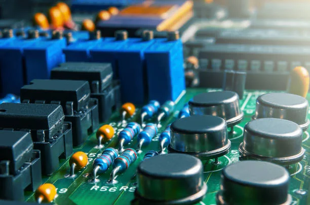
What Is A Capacitor
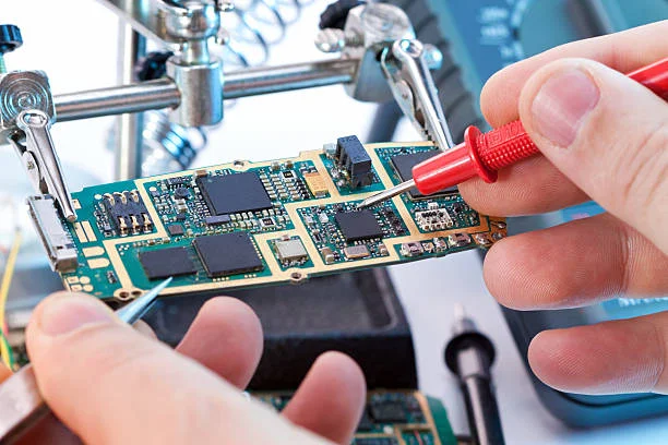
A capacitor is an electronic component that stores electrical energy in an electric field. It consists of two conductive plates separated by an insulating material called a dielectric. When a voltage is applied across the plates, opposite charges accumulate on them, creating an electric field between them. This stores energy in the form of electric potential energy.
Capacitors are commonly used in electronic circuits for various purposes, including filtering, smoothing, energy storage, coupling, and timing.
They come in various types, such as electrolytic capacitors, ceramic capacitors, tantalum capacitors, and film capacitors, each with its own characteristics and applications. Capacitors are characterized by their capacitance, measured in farads (F), which indicates how much charge it can store per unit voltage.
How to Measure Capacitor
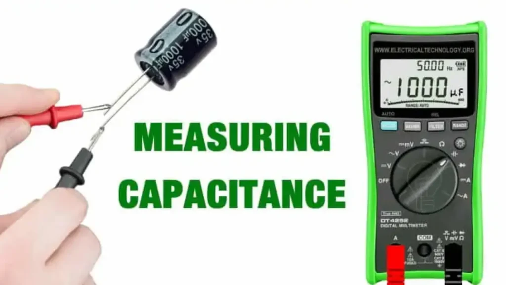
Capacitance, measured in Farads (F), quantifies a capacitor’s ability to store electrical charge. To accurately measure capacitance, specialized tools are often employed.
Then let’s say how are capacitors measured in the following:
Common Methods for Measuring Capacitance
Digital Multimeter (DMM):
- Direct Measurement: Many modern DMMs have a capacitance measurement function. Simply select the capacitance mode and connect the capacitor’s leads to the multimeter’s probes.
- Indirect Measurement: For DMMs without a direct capacitance mode, you can use the RC time constant method. This involves charging the capacitor through a known resistor and measuring the time it takes to discharge to a specific voltage.
LCR Meter:
- LCR meters are specifically designed to measure inductance (L), capacitance (C), and resistance (R). They provide precise measurements and are often used in laboratory settings.
Oscilloscope:
- By analyzing the waveform of a capacitor charging or discharging circuit, an oscilloscope can indirectly determine capacitance.7 This method requires more technical expertise and calculations.
Safety Precautions:
- Discharge the Capacitor: Always discharge a capacitor before handling it. A large capacitor can hold a dangerous charge, even after the power is off.8
- Use Proper Tools: Ensure that your measurement tools are calibrated and in good working condition.
- Follow Safety Guidelines: Adhere to electrical safety guidelines, especially when working with high voltages.9
Additional Tips:
- Consider the Capacitor’s Type: The type of capacitor (electrolytic, ceramic, etc.) can influence measurement accuracy.
- Check for ESR: Equivalent Series Resistance (ESR) can affect a capacitor’s performance, especially at higher frequencies. Some measurement tools can measure ESR.
- Calibrate Your Equipment: Regular calibration ensures accurate measurements.
By following these guidelines and using appropriate tools, you can accurately measure capacitance and troubleshoot electronic circuits effectively.
Capacitor Measurement Units
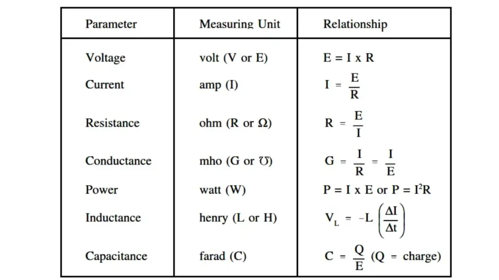
The standard unit of measurement for capacitance is the farad (F). However, due to the large magnitude of a farad, smaller units are commonly used in practical applications:
- Microfarad (µF): One millionth of a farad.
- Nanofarad (nF): One billionth of a farad.
- Picofarad (pF): One trillionth of a farad.
These smaller units are more practical for measuring the capacitance of most electronic components.
How to Measure Capacitor
Digital Multimeter: A digital multimeter is the go-to tool for measuring capacitors. It can measure capacitance directly and quickly, allowing you to assess a capacitor’s health. With its easy-to-read digital display, it helps you determine whether a capacitor is within its rated value.
Whether you’re working with smaller circuits or large systems like capacitor banks in substations, this tool provides essential measurements for efficient diagnostics.
Other Essential Tools: Safety gloves protect you when handling capacitors and working around electrical components. A screwdriver is crucial for discharging capacitors safely, preventing any potential shocks during measurement.
Wire cutters come in handy for removing faulty capacitors or cutting wires to isolate components for testing. These basic tools are essential for both safety and accurate capacitor measurement in any electrical setting.
Optional Tools: An LCR meter provides more precise readings than a standard multimeter, measuring inductance, capacitance, and resistance with higher accuracy. This tool is ideal for testing the ESR (Equivalent Series Resistance) of capacitors, offering deeper insight into their performance.
While not required for basic tests, an LCR meter can be invaluable when working with complex systems like capacitor banks in substations, where precision is crucial.
How to Measure Capacitor
Always turn off the power before testing a capacitor to prevent electrical shocks and avoid damaging your multimeter or other equipment. To safely discharge a capacitor, use a screwdriver with an insulated handle to short the terminals, ensuring no voltage remains.
If you’re working with high-voltage systems, such as those in industrial settings or capacitor banks in substations, it’s best to call in a professional to handle the testing and avoid serious risks.
How to Measure Capacitor With Multimeter

Certainly! Measuring a capacitor with a multimeter can be done effectively if you follow a series of steps. Below is a detailed guide on how to measure a capacitor using a multimeter, with each step clearly marked with an H3 heading.
Gather the Necessary Tools
Before you begin measuring a capacitor, ensure you have the following tools:
- Digital Multimeter (DMM): Make sure your multimeter has a capacitance measurement function (often indicated by a symbol resembling two parallel lines with a gap).
- Safety Gear: Depending on the capacitor’s rating, it may be necessary to wear safety glasses and gloves.
- Capacitor: The capacitor you wish to measure, which should be disconnected from any circuit to ensure safety and accurate measurements.
Discharge the Capacitor Safely
Before measuring a capacitor, it is essential to ensure it is discharged to avoid electric shock and damage to the multimeter:
- Short the Terminals: Use a resistor (typically a 1kΩ to 10kΩ resistor) or a multimeter set to measure resistance. Connect the resistor across the capacitor terminals for several seconds to safely discharge it.
- Caution: If it’s a large capacitor (high capacitance and voltage), use an insulated tool to short the terminals with caution.
- Check for Voltage: After discharging, use the multimeter set to measure voltage to check if any residual voltage remains. A reading close to 0V indicates the capacitor is discharged.
Set the Multimeter to Capacitance Mode
Once the capacitor is discharged and safe to handle, you’ll need to prepare your multimeter:
- Turn on the Multimeter: Power up your digital multimeter.
- Select Capacitance Mode: Rotate the dial or press the button (if applicable) to select the capacitance measurement mode, usually indicated by “C” or a capacitor symbol (||).
Connect the Multimeter Probes to the Capacitor
Now, you are ready to connect the multimeter to measure the capacitor’s capacitance:
- Identify the Terminals: Determine the positive (+) and negative (-) terminals of the capacitor, particularly if it is polarized (like electrolytic capacitors).
- Connect the Probes:
- For Non-Polarized Capacitors: Connect the red probe to one terminal and the black probe to the other terminal without worrying about polarity.
- For Polarized Capacitors: Ensure the red probe connects to the positive terminal and the black probe to the negative terminal.
Read the Measurement
After connecting the multimeter probes, observe the readings:
- Wait for Stability: The reading may fluctuate briefly before stabilizing. Wait a few seconds for the multimeter to provide a stable reading.
- Record the Capacitance Value: The display should show the capacitance in microfarads (μF), nanofarads (nF), or picofarads (pF) depending on the capacitor type.
Compare with Rated Value
Once you have obtained the measurement, compare it with the capacitor’s rated value, which can usually be found printed on the capacitor’s body. Here’s how you can interpret the results:
- Within Tolerance: If the measured capacitance is within the rated tolerance (often ±10% or ±20%), the capacitor is likely still good.
- Out of Range: If the reading is significantly lower than the rated value, the capacitor may be faulty and should be replaced.
Disconnect the Probes and Power Off the Multimeter
After taking the measurement, follow these steps to conclude:
- Remove the Probes: Carefully disconnect the multimeter probes from the capacitor terminals.
- Turn Off the Multimeter: Power down the multimeter to conserve battery life.
Dispose of Faulty Capacitors (if necessary)
If the capacitor has been determined to be faulty, proper disposal is essential:
- Check Local Guidelines: Look up regulations for disposing of electronic components in your area, especially for capacitors that may contain hazardous materials.
- Use a Designated E-Waste Facility: Take the faulty capacitor to an electronic waste recycling center.
By following these carefully outlined steps, you can measure a capacitor accurately and safely using a multimeter. If you have any more questions or need further clarification, feel free to ask!
How To Measure Capacitor In Circuit
In-Circuit vs. Out-of-Circuit Testing:
In-circuit testing involves measuring the capacitor while it remains connected to the circuit, allowing you to check if it’s still performing its function within the system. In contrast, out-of-circuit testing gives a clearer reading by isolating the capacitor from other components, ensuring a more accurate measurement without interference. Both methods have their place, but in-circuit testing is faster for initial diagnostics.
Accuracy of In-Circuit Measurements:
In-circuit measurements may be less accurate due to the influence of surrounding components. Other elements like resistors, inductors, and diodes can affect the readings, leading to a higher chance of error. Despite this, in-circuit testing can still identify obvious issues, such as if the capacitor is completely shorted or open, which can help narrow down potential circuit problems quickly.
Using a Multimeter In-Circuit:
When measuring a capacitor in-circuit, set your multimeter to the capacitance mode. Connect the probes to the capacitor’s terminals—red to positive and black to negative. While the capacitor is part of the circuit, you may not get a perfect reading, but a significant deviation from the rated value indicates a potential issue. This method helps detect capacitors that are failing to perform their function within the circuit.
Identifying Faulty Capacitors in Circuit:
Faulty capacitors in-circuit can often be identified by abnormal readings on the multimeter. If the capacitance is far below the rated value, or if the multimeter shows an open or short circuit, the capacitor may be bad. For more precision, testing the capacitor out of circuit is recommended, but in-circuit testing serves as a useful initial step for detecting problems before deciding on further actions.
How to Measure a Capacitor With an Oscilloscope
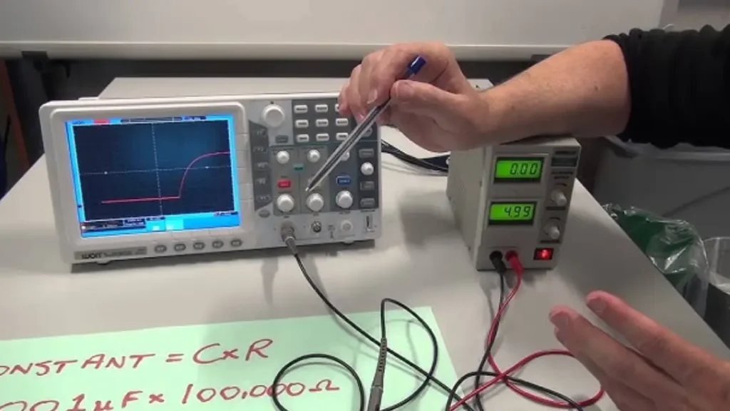
To measure a capacitor with an oscilloscope, you typically want to observe its behavior in a circuit, usually by applying a voltage and analyzing the waveform. Here’s a step-by-step guide:
Materials Needed:
- Oscilloscope
- Function Generator (or signal generator)
- Capacitor (the one you’re testing)
- Resistor (optional for more controlled measurements)
- Probes (to connect to the circuit)
Steps about how to measure voltage across a capacitor with an oscilloscope:
1. Set Up the Circuit:
- Connect the capacitor to the circuit with the oscilloscope probes.
- A common setup is to create an RC (resistor-capacitor) charging circuit. You can use a resistor in series with the capacitor, powered by a function generator.
- Connect one oscilloscope probe across the capacitor (or across the resistor if you’re measuring the voltage drop across it).
2. Configure the Oscilloscope:
- Set the oscilloscope time base (horizontal scale) to view a few cycles of the waveform.
- Set the voltage scale (vertical scale) so that you can clearly see the voltage change across the capacitor.
- Set the trigger mode to Edge Trigger with a positive slope (rising edge).
3. Apply a Signal (Using Function Generator):
- Set your function generator to provide a square wave (which is common for testing capacitors). The square wave should have a frequency around 1 kHz to 100 kHz for a basic test.
- The voltage amplitude should be chosen based on the capacitor rating (e.g., 5V or 10V).
4. Observe the Waveform:
- On the oscilloscope, you’ll see the capacitor charge and discharge as the signal cycles. A charging capacitor follows an exponential curve as it charges up to the supply voltage and then discharges when the signal switches off.
- The voltage across the capacitor will rise exponentially during charging and fall exponentially during discharging.
5. Measure Key Parameters:
- Time Constant (τ): For an RC circuit, the time constant is given by: τ=R×C\tau = R \times C The time constant determines how quickly the capacitor charges or discharges.
- On the oscilloscope, you can measure the time it takes for the voltage to rise to approximately 63% of its final value (charging) or fall to 37% (discharging).
- This time is roughly the time constant, τ\tau.
6. Determine the Capacitance:
- If you know the resistance RR and measure the time constant τ\tau, you can calculate the capacitance CC using the formula: C=τRC = \frac{\tau}{R}
- For a more accurate result, ensure that the resistor is chosen to match the expected charging times for your capacitor.
Example:
- If your measured time constant is 10 ms and your resistor is 1 kΩ, the capacitance will be: C=10 ms1 kΩ=10μFC = \frac{10\text{ ms}}{1 \text{ kΩ}} = 10 \mu F
Additional Tips:
- If you want to test the capacitor’s behavior at different frequencies, adjust the function generator’s frequency and observe the capacitor’s response.
- Parallel or Series Testing: If you’re testing a capacitor as part of a complex circuit, make sure to account for the rest of the components in the system (such as resistors, other capacitors, or inductors).
This method helps you visualize the capacitor’s charging and discharging cycles, which can give insights into its performance.
Conclusion
Measuring a capacitor accurately is essential for maintaining the efficiency of your circuits and systems. By following the step-by-step guide on how to measure capacitor, you can confidently identify faulty components, troubleshoot circuit issues, and ensure reliable performance.
Whether you’re working with low-voltage or high-voltage systems, understanding the proper tools and techniques is crucial. If you’re in need of high-quality capacitors for your projects, quote your next capacitor from Weishi today for unmatched reliability and performance.