Welcome to the electrifying world of capacitor reactance!
In this detailed article, we’ll embark on a journey to unravel the mysteries surrounding capacitor reactance, exploring its significance, functionality, and real-world applications.
What is Capacitor Reactance
Capacitive reactance is the opposition a capacitor offers to the flow of alternating current (AC). It’s measured in ohms, just like resistance.
Unlike resistance, which dissipates energy as heat, capacitive reactance stores and releases energy in an electric field.
Understanding Capacitors
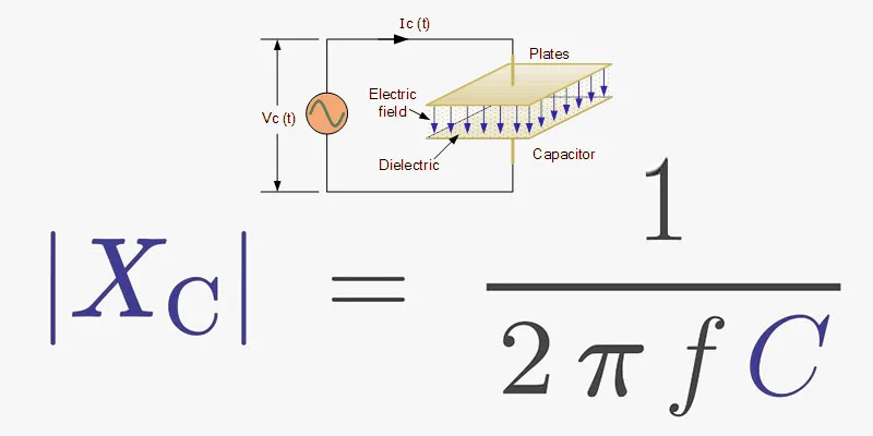
Before delving into capacitor reactance, let’s grasp the fundamentals of capacitors. A capacitor is an essential electronic component that stores electrical energy in an electric field. It consists of two conductive plates separated by an insulating material known as a dielectric. Capacitors come in various types and sizes, each designed for specific applications ranging from filtering to energy storage.
Capacitor Reactance Demystified
Capacitive Reactance Defined
Capacitive reactance, denoted by 𝑋𝐶XC, is a measure of a capacitor’s opposition to alternating current (AC). Unlike resistance in direct current (DC) circuits, which dissipates energy, capacitive reactance results from the capacitor’s ability to store and release energy, leading to a phase shift between voltage and current.
Factors Influencing Capacitor Reactance
Capacitive reactance (𝑋𝐶XC) is influenced by the frequency (𝑓f) of the alternating current and the capacitance (𝐶C) of the capacitor. Mathematically, it is represented by the capacitor formula 𝑋𝐶=12𝜋𝑓𝐶XC=2πfC1, where 𝜋π is a mathematical constant approximately equal to 3.14.
Actual Case
| Example | Frequency (Hz) | Capacitance (mF) | Capacitive Reactance (Ω) |
|---|---|---|---|
| 1 | 50 | 40 | 0.07961 |
| 2 | 100 | 1000 | 0.0015 |
Capacitor Reactance Calculator
Here’s a simple online calculator to determine capacitive reactance:
66pacific:
This calculator allows you to input the frequency and capacitance values, and it will calculate the capacitive reactance in ohms.
How to Calculate Reactance of a Capacitor
- Enter the frequency in Hertz (Hz).
- Enter the capacitance in Farads (F), microfarads (uF), nanofarads (nF), or picofarads (pF).
- Click the “Calculate” button.
The calculator will display the capacitive reactance value.
Note:
- Capacitive reactance is inversely proportional to frequency is a complex number with a phase angle of -90 degrees.
Alternative: You can also use general-purpose scientific calculators or online tools to calculate capacitive reactance by directly inputting the formula Xc = 1 / (2πfC).
The formula used to calculate capacitive reactance is:
𝑋𝑐=12𝜋𝑓𝐶Xc=2πfC1
Where:
𝑋𝑐Xc is the capacitive reactance in ohms (Ω),
𝑓f is the frequency in hertz (Hz),
𝐶C is the capacitance in millifarads (mF).
Capacitive Reactance in AC Circuit
In an AC (alternating current) circuit, capacitors exhibit a property called capacitive reactance. This refers to the opposition or resistance that a capacitor presents to the flow of alternating current. It’s symbolized by 𝑋𝐶XC and is measured in ohms (ΩΩ).
The formula to calculate capacitive reactance is:
𝑋𝐶=12𝜋𝑓𝐶XC=2πfC1
Where:
- 𝑋𝐶XC is the capacitive reactance.
- 𝑓f is the frequency of the alternating current in hertz (Hz).
- 𝐶C is the capacitance of the capacitor in farads (F).
- 𝜋π (pi) is a mathematical constant, approximately equal to 3.14159.
As the frequency of the AC current increases, the capacitive reactance decreases, allowing more current to flow through the capacitor. Conversely, as the frequency decreases, the capacitive reactance increases, limiting the current flow.
Reactance Formula for Capacitor and Inductor
Reactance is the opposition offered by a circuit component (capacitor or inductor) to the flow of alternating current (AC). It’s measured in ohms (Ω).
Capacitive Reactance (Xc)
The formula for capacitive reactance is:
Xc = 1 / (2πfC)
Where:
Xc: Capacitive reactance in ohms (Ω)f: Frequency of the AC signal in Hertz (Hz)C: Capacitance in Farads (F)
Inductive Reactance (Xl)
The formula for inductive reactance is:
Xl = 2πfL
Where:
Xl: Inductive reactance in ohms (Ω)f: Frequency of the AC signal in Hertz (Hz)L: Inductance in Henrys (H)
Key points to remember:
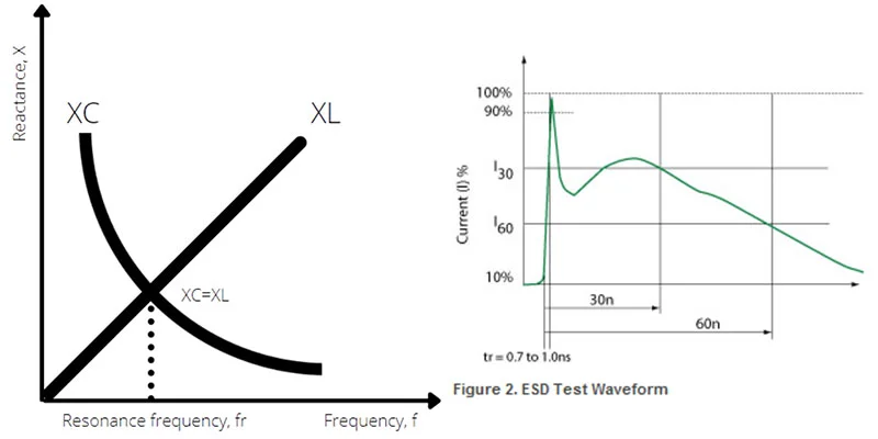
- Capacitive Reactance: As the frequency increases, capacitive reactance decreases.
- Inductive Reactance: As the frequency increases, inductive reactance increases.
- Phase Difference: Capacitive reactance causes the current to lead the voltage by 90 degrees, while inductive reactance causes the current to lag the voltage by 90 degrees.
By understanding these formulas and concepts, you can analyze and design AC circuits effectively.
What is the Capacitive Reactance of the Capacitor
To calculate the capacitive reactance, we need to know the capacitance (C) of the capacitor and the frequency (f) of the AC signal.
Formula for capacitive reactance (Xc):
Xc = 1 / (2πfC)
Where:
- Xc is the capacitive reactance in ohms (Ω)
- f is the frequency in Hertz (Hz)
- C is the capacitance in Farads (F)
Example: If you have a capacitor with a capacitance of 10 microfarads (10 x 10^-6 F) and the frequency of the AC signal is 60 Hertz, the capacitive reactance would be:
Xc = 1 / (2π * 60 * 10^-6) ≈ 265.26 ohms
Please provide the capacitance of your capacitor and the frequency of the AC signal, and I can calculate the exact capacitive reactance for you.
Note:
- Capacitive reactance is inversely proportional to frequency. As the frequency increases, the reactance decreases, allowing more current to flow through the capacitor.
- Capacitive reactance is a complex number with a phase angle of -90 degrees.
I hope this helps!
What Two Factors Determine the Capacitive Reactance of a Capacitor
The two factors that determine the capacitive reactance of a capacitor are:
- Frequency (f): The higher the frequency of the AC signal, the lower the capacitive reactance. This is because at higher frequencies, the capacitor charges and discharges more rapidly, reducing its opposition to current flow.
- Capacitance (C): The greater the capacitance of the capacitor, the higher the capacitive reactance. A larger capacitor can store more charge, which means it offers more opposition to changes in voltage and current.
The relationship between capacitive reactance (Xc), frequency (f), and capacitance (C) is given by the following formula:
Xc = 1 / (2πfC)
Where:
- Xc is the capacitive reactance in ohms (Ω)
- f is the frequency in Hertz (Hz)
- C is the capacitance in Farads (F)
Applications of Capacitor Reactance
| Application | Product Examples |
|---|---|
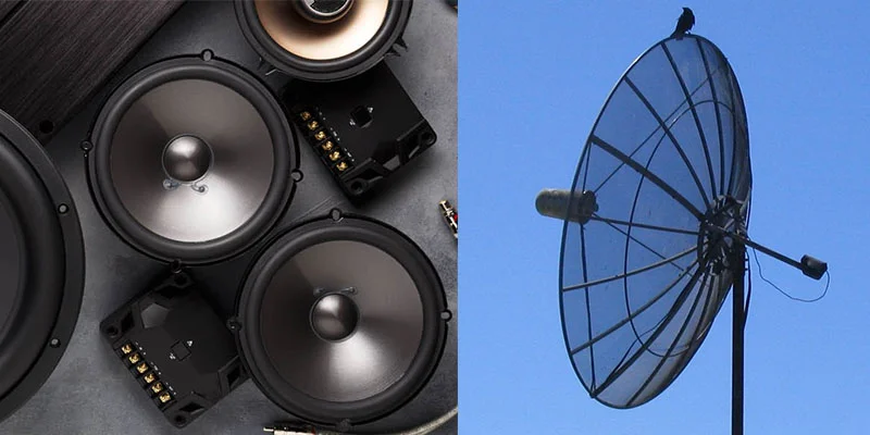
| Audio Systems | Stereo Systems, Headphones, Car Audio Systems |
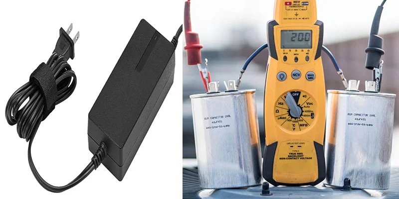
| Power Supplies | Laptop Chargers, LED Lights, Home Appliances |
| Communication Devices | Smartphones, Wireless Routers, Satellite Receivers |
| Industrial Equipment | Motor Drives, HVAC Systems, Industrial Lighting |
Filtering Applications
Capacitor reactance finds extensive applications in electronic filtering circuits, where it selectively allows certain frequencies to pass while attenuating others. This property is leveraged in audio systems, power supplies, and communication devices to remove unwanted noise and interference.
Audio Systems:
In speakers and amplifiers, capacitors are used to filter out low-frequency noise, ensuring that only the desired audio signals are amplified and transmitted.
Power Supplies:
Capacitors in power supply units filter out high-frequency noise and fluctuations from the main power source, ensuring a stable and clean output voltage for electronic devices.
Communication Devices:
Capacitors are employed in radio frequency (RF) circuits to filter out unwanted frequencies and interference, allowing clear communication signals to be transmitted and received.
Power Factor Correction
In industrial and commercial settings, capacitor banks are employed for power factor correction to improve the efficiency of electrical systems. By introducing capacitive reactance, power factor correction capacitors offset the effects of inductive loads, thereby minimizing reactive power and optimizing energy utilization.
Industrial Equipment:
In factories and manufacturing plants, capacitor banks are installed to improve the power factor of electrical systems. By reducing reactive power, these capacitors optimize energy consumption and minimize utility costs.
Commercial Buildings:
Capacitor banks installed in commercial buildings help improve the efficiency of electrical systems, leading to lower electricity bills and reduced environmental impact.
Frequency-dependent Circuits
Capacitor reactance plays a crucial role in frequency-dependent circuits such as oscillators, resonant circuits, and phase shifters. These circuits exploit the frequency-dependent nature of capacitors to achieve specific voltage phase relationships or resonance conditions, enabling applications in signal generation and modulation.
Oscillators:
Capacitors are integral components in electronic oscillators used in clocks, radios, and electronic instruments to generate continuous waveforms at specific frequencies.
Resonant Circuits:
Capacitors in resonant circuits are utilized in applications like radio tuning circuits and magnetic resonance imaging (MRI) systems to achieve resonance at desired frequencies for signal processing and transmission.
Phase Shifters:
Capacitors are employed in phase shifters used in audio mixers and signal processing equipment to alter the phase relationship between input and output signals, enabling creative sound manipulation and effects.
Investigating Capacitor Reactance in Practice
Phase Relationship Between Voltage and Current
In AC circuits, capacitor reactance leads to a phase shift between voltage and current. Unlike resistive elements where voltage and current are in phase, capacitors exhibit a 90-degree leading phase shift, making them essential for power factor correction and voltage regulation.
Implications on Circuit Behavior
The presence of capacitor reactance alters the impedance of an AC circuit, affecting its overall behavior. Understanding the interplay between capacitive reactance, inductive reactance, and resistance is crucial for designing efficient and stable electrical systems.
Capacitive Reactance Challenges and Solutions?
Challenges Associated with Capacitive Reactance
Resonance Phenomena:
Capacitive reactance can lead to resonance effects when combined with inductive reactance in AC circuits. Resonance occurs at specific frequencies where the capacitive and inductive reactances cancel each other out, resulting in voltage amplification or current surges.
Voltage Transients:
Rapid changes in voltage levels, known as transients, can occur due to sudden variations in capacitive reactance. These transients may pose challenges to the stability and reliability of electrical systems, potentially causing equipment damage or malfunctions. It is very important to determine the capacitive reactance of the capacitor
Harmonic Distortion:
In AC circuits with non-linear loads, such as power electronics or electrical machinery, capacitive reactance can contribute to harmonic distortion. Harmonics are multiples of the fundamental frequency and can lead to undesirable effects such as overheating, equipment malfunction, and interference with other electrical devices.
Solutions to Mitigate Capacitive Reactance Challenges
Damping Circuits:
Implementing damping circuits, such as resistors or inductors, can help attenuate resonance effects by dissipating excess energy and damping oscillations in the electrical system. These circuits are designed to absorb energy and prevent voltage amplification at resonance frequencies.
Impedance Matching:
Employing impedance matching techniques ensures optimal power transfer between electrical components and systems, minimizing reflections and enhancing system efficiency. By matching the impedance of capacitive and inductive elements, impedance matching mitigates resonance effects and reduces voltage transients.
Resonance Suppression Techniques:
Utilizing active or passive resonance suppression techniques, such as notch filters or phase-shifting networks, can effectively suppress resonance phenomena in AC circuits. These techniques are designed to selectively attenuate specific frequencies associated with resonance, maintaining system stability and performance.
By addressing these challenges with proactive solutions, engineers can mitigate the adverse effects of capacitive reactance and ensure the reliable operation of electrical systems across diverse applications.
FAQ about Capacitor Reactance
What is the significance of capacitor reactance in AC circuits?
Capacitor reactance determines the behavior of capacitors in AC circuits, influencing factors such as impedance, phase shift, and power distribution.
How does capacitor reactance differ from resistance?
While resistance remains constant in DC circuits, capacitor reactance varies with the frequency of the applied AC voltage, offering dynamic opposition to the flow of current.
Can capacitors store energy in AC circuits?
Yes, capacitors can store and release energy in AC circuits, albeit with variations in reactance and charging/discharging dynamics compared to DC circuits.
What role does capacitance play in capacitor reactance?
Capacitance directly influences the magnitude of capacitor reactance, with higher capacitance values resulting in greater opposition to current flow at a given frequency.
How does capacitor reactance affect power factor correction?
Capacitor reactance enables the compensation of reactive power in AC circuits, improving power factor and overall system efficiency in industrial and commercial applications.
What are some common challenges associated with capacitor reactance in electrical circuits?
Challenges such as resonance effects, voltage transients, and harmonic distortion may arise due to capacitor reactance, requiring careful design and mitigation strategies.