Capacitors are fundamental components in nearly every electronic device. From powering your smartphone to stabilizing signals in complex machinery, capacitors store and release electrical energy, making them crucial to the operation of circuits. Whether you’re a hobbyist, engineer, or technician, understanding capacitor markings is essential to selecting the right component for your project.
Capacitor markings serve as a vital tool in identifying the component’s key specifications, such as capacitance value, voltage rating, and polarity. Without a clear understanding of these markings, choosing the correct capacitor could lead to circuit malfunction, inefficiency, or even damage.
In this guide, we’ll delve into the various types of capacitor markings, from basic capacitance values to more complex codes, and explain how to interpret them accurately. Whether you’re working with small surface-mount devices (SMD) or large electrolytic capacitors, this article will equip you with the knowledge needed to make informed decisions when reading capacitor markings.
What Are Components of Capacitor Markings
Capacitor markings typically contain several key components, each providing essential information about the capacitor’s properties. Understanding these components will help you interpret the markings more easily:
- Capacitance Value: This is the most crucial piece of information on a capacitor’s marking, telling you how much charge the capacitor can store. It is typically expressed in microfarads (µF), nanofarads (nF), or picofarads (pF).
- Voltage Rating: This indicates the maximum voltage that the capacitor can safely handle. Exceeding the voltage rating can lead to capacitor failure or even circuit damage.
- Tolerance: This refers to the allowable variation in the capacitor’s actual capacitance from the labeled value. Tolerance values are typically expressed as a percentage, such as ±5%, ±10%, or ±20%.
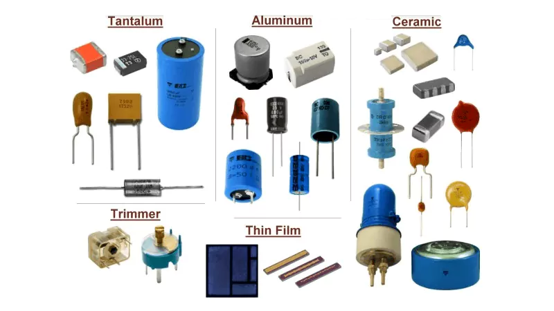
- Dielectric Material: The type of dielectric material used in the capacitor, such as ceramic, polyester, or tantalum, influences the capacitor’s performance in various environments.
- Polarity: For polarized capacitors, the polarity markings indicate which terminal is positive and which is negative. It’s essential to install the capacitor in the correct orientation to avoid malfunction or damage.
Polymer Capacitor Markings
Polymer capacitors, like other electronic components, carry markings that convey essential information about their characteristics and specifications. These markings are crucial for proper component selection, identification, and circuit design.
Common Polymer Capacitort Markings and Their Significance
Capacitance Value: This is the primary marking, indicating the capacitor’s ability to store electrical charge. It’s often expressed in microfarads (µF), nanofarads (nF), or picofarads (pF). Common notations include:
- Numerical: 10µF, 47nF, 220pF
- Alphanumeric: 104 (for 100,000 pF = 0.1µF), 473 (for 47,000 pF = 47nF)
Voltage Rating: This specifies the maximum DC voltage that the capacitor can withstand without breaking down. It’s crucial to select capacitors with voltage ratings that exceed the expected operating voltage in the circuit.
Tolerance: This indicates the permissible deviation of the actual capacitance value from the marked value. Common tolerances include ±5%, ±10%, and ±20%.
Manufacturer’s Code: This identifies the manufacturer of the capacitor. It can be a combination of letters and numbers.
Date Code: This indicates the manufacturing date of the capacitor. The format varies between manufacturers, but it often includes a combination of letters and numbers.
Polarity Indication: Polymer capacitors are often polarized, meaning they have a positive and negative terminal. This is crucial for correct connection in the circuit. Polarity is typically indicated by:
- A stripe or band on the negative terminal
- A minus sign (-) on the negative terminal
- A plus sign (+) on the positive terminal
Temperature Rating: This specifies the maximum operating temperature range of the capacitor.
Reading and Interpreting Markings
Decoding capacitor markings requires careful observation and a bit of knowledge about the coding conventions used by different manufacturers.
Example: A marking like “104K 25V” would typically indicate a 0.1µF capacitor with a 25V voltage rating and a 10% tolerance.
Importance of Accurate Markings
Accurate markings are essential for:
- Correct Component Selection: Choosing the right capacitor for a specific application is crucial for circuit performance and reliability.
- Circuit Design: Markings provide essential data for circuit design and simulation.
- Troubleshooting: In case of circuit malfunctions, markings help identify and replace faulty capacitors.
Note: Marking conventions can vary between manufacturers. Always refer to the manufacturer‘s datasheet for specific information on the markings used for their products.
Types and Formats of Capacitor Markings
Capacitor markings come in a variety of formats, depending on the type and size of the capacitor. These markings provide essential information that allows technicians and engineers to identify the component’s specifications. Understanding these formats is crucial when selecting or replacing capacitors in circuits.
1. Numerical Markings
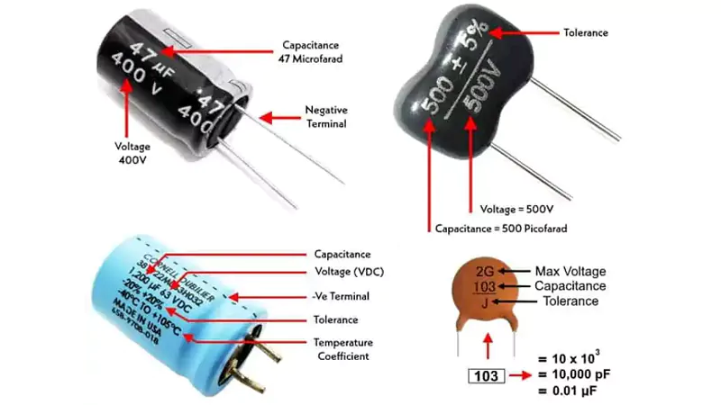
One of the most common formats for capacitor markings is the numerical code. This is typically a series of three or four digits, which represent the capacitance value and sometimes the tolerance.
- Three-digit code: The first two digits represent the significant figures, and the third digit indicates the number of zeros to add. For example, a marking of 104 means 10 followed by four zeros, or 100,000 pF (picofarads), which is equal to 0.1 µF (microfarads).
- Four-digit code: In some cases, a four-digit code may be used for more precise capacitance values. For example, 4701 means 47 followed by one zero, or 470 pF.
2. Letter and Symbol Codes
Some capacitors use letter codes to indicate specific characteristics, such as tolerance, voltage rating, or the type of dielectric material used. These letter codes are often combined with numbers to give full specifications.
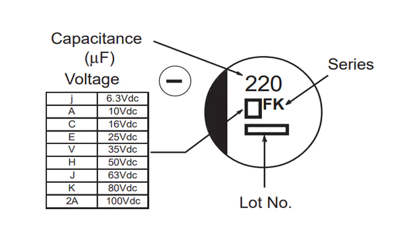
- Voltage Rating: Some capacitors mark the voltage rating using a letter code like V or WV (working voltage). For example, a capacitor with a marking of 25V indicates that the capacitor can safely operate at 25 volts.
- Tolerance: Tolerance is typically marked with a letter following the capacitance value. For example:
- J means ±5% tolerance.
- K means ±10% tolerance.
- M means ±20% tolerance.
- Dielectric Material: The type of dielectric material used in the capacitor may also be indicated by a letter code. Common types include:
- C for Ceramic
- E for Electrolytic
- T for Tantalum
3. Voltage and Capacitance Units
Capacitor markings often include units to specify the capacitance and voltage rating:
- Capacitance: Capacitance is usually marked in microfarads (µF), nanofarads (nF), or picofarads (pF). Some capacitors, particularly larger ones, may use a numerical code without units (e.g., 100 for 100 µF), while others clearly state the units (e.g., 1 µF, 100 pF).
- Voltage Rating: The voltage rating is typically indicated in volts (V). It’s important to note that capacitors should be used within the recommended voltage range to avoid failure or damage. For example, 16V indicates the capacitor’s maximum voltage rating.
4. Color Bands and Dots
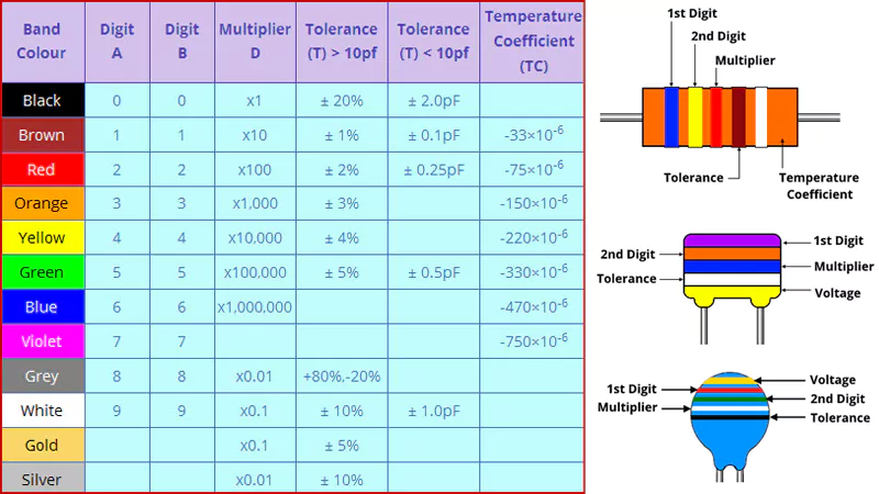
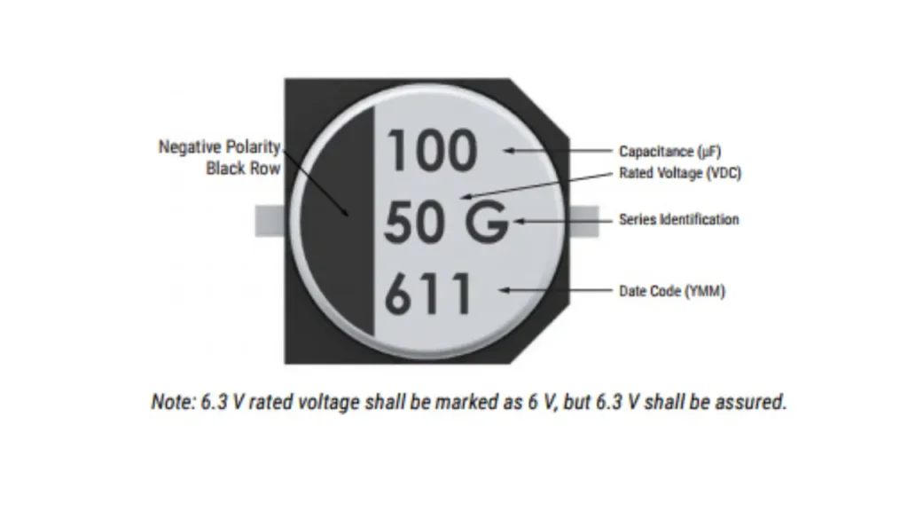
Some capacitors, especially older or higher-value ones, may use color bands or dots to indicate capacitance and tolerance values. This format is commonly seen in electrolytic capacitors, particularly larger ones with higher capacitance values.
For example:
- A color band system for an electrolytic capacitor may have three or more bands representing the capacitance value, with each band corresponding to a specific number.
5. SMD (Surface-Mount Device) Capacitor Markings
Surface-mount capacitors (SMD) have smaller, more compact markings due to their reduced size. These capacitors typically use a three-digit code similar to the one used for through-hole components, but in a more condensed format. For example, a marking of 105 on an SMD capacitor represents 1 µF (10 followed by 5 zeros).
Additionally, SMD capacitors may have a code for the manufacturer and other specifications like tolerance and voltage ratings printed directly on the surface.
6. Symbols and Additional Information
Capacitors may also have symbols or additional text that provide further information. Some of the most common symbols include:
- Polarity Symbols: For polarized capacitors, such as electrolytics, a negative sign (-) or a line next to the negative terminal indicates polarity.
- Capacitance Value and Tolerance: In some cases, the full capacitance and tolerance will be marked directly on the body of the capacitor. For example, 100µF ±20%.
Capacitor Markings Polarity
Polarity markings are essential when dealing with polarized capacitors. Incorrect installation of these capacitors can lead to circuit malfunction or even damage to the capacitor and the surrounding components. Understanding the polarity markings ensures that capacitors are installed in the correct orientation, maintaining the circuit’s reliability and safety.
Importance of Polarity Markings
Polarized capacitors, including electrolytic capacitors, tantalum capacitors, polymer capacitors, and others, have distinct positive and negative terminals. If installed incorrectly, these capacitors can fail, overheat, or even cause damage to the circuit. Therefore, it is critical to always identify and respect the polarity markings, especially for capacitors like SMD capacitors (Surface-Mount Devices) and film capacitors, which are commonly used in modern circuits.
Common Symbols for Identifying Polarity
Capacitors generally have markings that indicate which terminal is positive and which is negative. The following are common symbols and markings you’ll encounter for polarized capacitors:
Negative Terminal:
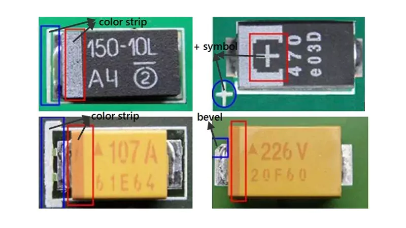
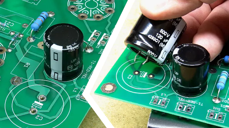
- The negative terminal is often marked with a minus sign (-) or a black stripe along the body. For example, tantalum capacitor markings often feature a stripe to indicate the negative terminal.
- In aluminum capacitor markings, the negative terminal is marked with a similar stripe, sometimes accompanied by the voltage rating.
Positive Terminal:
- The positive terminal is usually marked with a plus sign (+), and sometimes the positive lead is longer in the case of axial capacitor markings.
- For polymer capacitor markings, the positive lead is generally the unmarked or longer lead, while the negative terminal has a stripe.
Examples of Polarized Capacitors
Electrolytic Capacitors
Electrolytic capacitors, one of the most common types of polarized capacitors, have clear polarity markings.
- Markings: The negative lead is typically marked with a black stripe or a minus sign (-). The positive lead, which is often longer, is either unmarked or marked with a plus sign (+).
- Application: Used in power supply circuits, surface mount electrolytic capacitor markings will often include the capacitance value and voltage rating in a very compact format.
- Tantalum Capacitors
Tantalum capacitors, which are popular in miniaturized circuits, are also polarized. - Markings: Tantalum capacitor markings commonly feature a stripe or marking on the negative side, indicating the cathode. The anode (positive side) is unmarked or marked with a plus sign (+).
- SMD Tantalum Capacitor Markings: When used in SMD (Surface-Mount Device) applications, SMD tantalum capacitor markings are compact and may include a stripe or other marking on the negative side.
Polymer Capacitors
These capacitors are known for their improved characteristics compared to traditional electrolytics, such as better performance at high frequencies.
- Markings: Like electrolytics, polymer capacitor markings often include a stripe or minus sign (-) on the negative terminal. The positive terminal is typically the longer lead or unmarked.
- Applications: Polymer capacitors are commonly found in power circuits, where performance and stability are critical.
Aluminum Capacitors
Aluminum capacitor markings usually display a stripe with the negative polarity, while the positive side may be marked with a plus sign (+). These capacitors are widely used in power supply filtering applications.
Ceramic Capacitors
Ceramic capacitor markings vary based on the type, but most ceramic capacitors, especially ceramic disc capacitor markings, are non-polarized and do not require polarity markings. However, ceramic disc capacitors used in AC circuits may feature additional markings to indicate their voltage or tolerance specifications.
SMD Capacitors
SMD capacitor markings are generally smaller due to the reduced size of the components. SMD capacitor marking codes typically include a combination of numbers and letters, with the negative lead marked either with a stripe or a shorter lead.
For SMD tantalum capacitors, the SMD tantalum capacitor markings follow similar conventions, with a stripe indicating the cathode (negative terminal).
Super Capacitors and AC Capacitors
- Super Capacitors: These high-capacity capacitors are also polarized and may include super capacitor polarity markings that indicate the positive and negative leads. It’s crucial to install these capacitors with the correct polarity to avoid damage and ensure optimal performance.
- AC Capacitors: Some capacitors, particularly AC capacitors, are polarized for use in AC circuits. These often feature AC capacitor markings indicating the appropriate voltage and polarity. However, unlike DC polarized capacitors, AC capacitors are often marked with a specific tolerance for AC voltage.
How to Install Polarized Capacitors
When installing polarized capacitors on a printed circuit board (PCB), here are the key steps to follow:
- Double-check PCB Capacitor Polarity Markings: Always verify the PCB capacitor polarity markings to match the positive and negative terminals on the capacitor with the circuit design.
- Align Leads Correctly: For axial capacitors, the leads are straight, and for SMD capacitors, the leads or pads should align with the positive and negative markings on the PCB.
- Respect the Layout: Ensure that the capacitor’s positive and negative leads are properly inserted into the corresponding pads, avoiding the risk of incorrect installation.
Circuit Board Capacitor Polarity Markings
When working with capacitors on printed circuit boards (PCBs), understanding how capacitor polarity markings are handled is essential for ensuring proper installation and function. Incorrectly installing capacitors can lead to malfunction, damage, or even failure of the entire circuit. This section will explain how to identify capacitor polarity markings on circuit boards, and provide practical tips for installing capacitors correctly.
How Capacitor Markings Are Handled on Circuit Boards
On a circuit board, capacitor markings are used to indicate the correct orientation for installing polarized capacitors, such as electrolytic capacitors, tantalum capacitors, and polymer capacitors. These capacitors have positive and negative terminals that must be correctly aligned with the PCB’s design to ensure they function as intended.
PCB manufacturers typically include polarity markings on the board to guide correct installation. These markings are usually found near the capacitor’s footprint or pads, and they include:
Markings on the PCB:
- Positive Marking: Often represented by a “+” symbol, indicating where the positive terminal of the capacitor should be placed.
- Negative Marking: Typically denoted with a “-“ symbol or sometimes a black stripe. The negative terminal of the capacitor should align with this marking. In some cases, the negative pad may be shorter than the positive pad to ensure proper orientation.
Capacitor Footprint:
The physical layout of the pads or holes in the capacitor’s footprint on the PCB also aids in identifying polarity. The positive pad may be larger than the negative pad, or the negative lead may be on the left side of the footprint (for through-hole capacitors).
Capacitor Orientation Indicators:
On some boards, polarity indicators can include marks such as arrows pointing to the negative pad or a square or circle around the positive or negative pads to further clarify the correct installation direction.
How to Identify Polarity on a Circuit Board
Identifying polarity on a PCB is relatively straightforward once you know where to look. Here’s how to read PCB capacitor polarity markings:
- Look for the Polarity Symbols:
Check for the “+” and “-“ symbols next to the capacitor pads. These markings directly indicate where to place the positive and negative leads of the capacitor. - Check the Pad Sizes:
For many polarized capacitors, the negative pad is usually smaller than the positive pad. This size difference can help you identify the correct orientation, especially for through-hole capacitors. - Verify the Stripes on Electrolytic Capacitors:
If you are working with electrolytic capacitors, check for a black stripe or marking running along the side of the capacitor body. This stripe marks the negative terminal. Ensure this stripe aligns with the negative pad on the PCB. - Use the Positive Lead (for Axial Capacitors):
For axial-leaded capacitors, the longer lead usually indicates the positive terminal, which should correspond with the positive pad on the PCB. If no markings are provided, the longer lead is typically a good clue. - For Surface-Mount Capacitors (SMD):
SMD capacitors often have small markings, such as a small dot or a line near the terminal closest to the negative side. Additionally, the negative terminal is often marked with a small square pad, while the positive side is generally indicated by a round pad.
Frequently Asked Questions (FAQs)
What is capacitor polarity?
Capacitor polarity refers to the positive (+) and negative (-) terminals of a polarized capacitor. It’s crucial to install these capacitors with the correct orientation to prevent damage or malfunction in a circuit
How can I tell if a capacitor is polarized or non-polarized?
Polarized capacitors, such as electrolytic and tantalum capacitors, have distinct markings (e.g., a stripe, minus sign, or shorter lead for the negative terminal) indicating their polarity. Non-polarized capacitors, like ceramic capacitors, typically have no such markings, as they can be installed in either orientation.
How do I decode the numerical markings on a capacitor?
Capacitors often display a series of numbers that represent the capacitance value and voltage rating. The first two digits indicate the capacitance value in picofarads (pF), and the third digit specifies the number of zeros to add. For example, a marking of 104 means 10 followed by 4 zeros, or 100,000 pF (100nF).
What are common mistakes when reading capacitor markings?
Some common mistakes include confusing the positive and negative terminals on polarized capacitors, misreading the voltage rating, or misunderstanding the capacitance value if the numerical code is unfamiliar. Always double-check the marking codes and symbols.
How do I read markings on small capacitors like SMD?
SMD capacitors use compact markings to indicate their value and polarity. Look for small dots, lines, or other symbols on the capacitor body. SMD capacitors may also have a negative marking or a square pad on the PCB to indicate polarity. Use a magnifying tool to clearly read the markings on small SMD components.
Conclusion
In conclusion, understanding capacitor markings is essential for anyone working with electronic components. These markings provide crucial information about the type, value, and polarity of capacitors, which can significantly affect the performance and safety of your circuit. By correctly interpreting the capacitor markings polarity, capacitor value markings, and other indicators, you ensure that capacitors are installed properly, avoiding potential damage or malfunction.
As you apply this knowledge, remember that selecting the right capacitors for your application goes beyond just matching the value. It involves paying close attention to polarity markings, size, and type, especially when working with polarized capacitors such as electrolytic capacitors, tantalum capacitors, and SMD capacitors. Always take the time to carefully read the markings on each capacitor to ensure a successful and reliable installation.