As a supplier of capacitors, I’ve encountered countless questions about the voltage across capacitor and how they function within electrical circuits. Whether you are an engineer, a hobbyist, or simply curious about electronics, understanding the concept of voltage across capacitors is essential.
What is a Capacitor
To begin with, let’s define what a capacitor is. A capacitor is a two-terminal passive electronic component that stores electrical energy in an electric field. It is commonly used in various applications, including energy storage, filtering, and signal coupling.
Capacitors come in numerous shapes, sizes, and specifications. They can be found in everything from small electronic devices to large power supplies. The fundamental principle behind a capacitor’s operation is based on the ability of its two conductive plates, separated by an insulating material (dielectric), to accumulate and store electrical charge.
Voltage Across a Capacitor
How to find voltage across a capacitor?
A capacitor is a passive electronic component that stores electrical energy in an electric field. It consists of two conductive plates separated by a dielectric material. When a voltage is applied across the terminals of a capacitor, an electric field is established between the plates, causing charge to accumulate on each plate.
The Voltage-Charge Relationship
The relationship between the voltage across a capacitor (V) and the charge stored on its plates (Q) is given by the following equation:
This is the voltage across capacitor formula below:
Q = CV
Where:
- Q is the charge stored in coulombs (C)
- C is the capacitance in farads (F)
- V is the voltage across the capacitor in volts (V)
This equation tells us that the voltage across a capacitor is directly proportional to the charge stored on its plates.
Capacitor Behavior in DC Circuits
- Charging: When a DC voltage source is connected to an uncharged capacitor, current flows through the circuit, charging the capacitor.9 As the capacitor charges, the voltage across its plates increases, and the current flowing through the circuit decreases.
- Steady-State: Once the capacitor is fully charged, the voltage across its plates equals the source voltage, and the current through the circuit becomes zero. The capacitor acts as an open circuit in steady-state DC conditions.
- Discharging: When the voltage source is removed, the capacitor discharges through a resistor or other load. The voltage across the capacitor decreases exponentially with time.
Capacitor Behavior in AC Circuits
In AC circuits, capacitors exhibit impedance, which is the opposition to the flow of alternating current. The impedance of a capacitor is inversely proportional to the frequency of the AC signal. This property makes capacitors useful for filtering and frequency-selective circuits.
Key Points to Remember:
- Capacitors store energy in an electric field.
- The voltage across a capacitor is directly proportional to the charge stored on its plates.
- Capacitors act as open circuits in DC steady-state conditions.
- Capacitors exhibit impedance in AC circuits.
By understanding these fundamental concepts, you can effectively analyze and design circuits involving capacitors.
Capacitor to Voltage
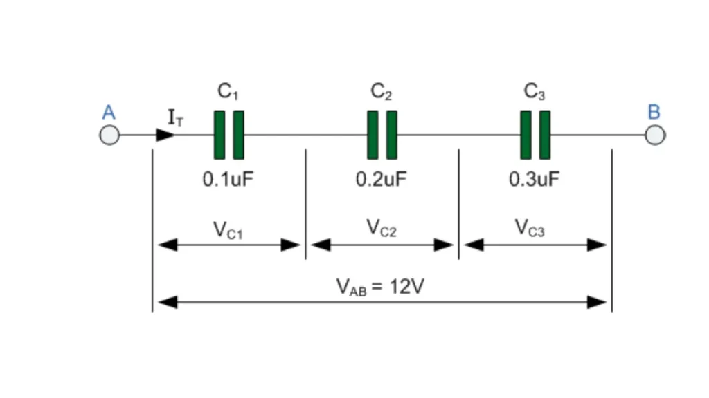
The relationship between the voltage across a capacitor and the charge stored on it is given by:
V = Q / C
where:
- V is the voltage across the capacitor
- Q is the charge stored on the capacitor plates
- C is the capacitance of the capacitor
In simpler terms:
- Voltage is directly proportional to the charge: More charge stored on the capacitor plates results in a higher voltage across it.
- Capacitance influences the voltage: A larger capacitance can store more charge for the same voltage, or equivalently, a given charge will result in a lower voltage across a larger capacitor.
Key Points:
- Capacitance (C): This is a property of the capacitor itself, determined by its physical characteristics (like plate area, distance between plates, and the dielectric material between them).
- Charge (Q): The amount of electrical charge stored on the capacitor plates.
- Voltage (V): The electrical potential difference between the capacitor plates.
Example:
If a capacitor has a capacitance of 10 microfarads (μF) and stores a charge of 50 microcoulombs (μC), the voltage across the capacitor would be:
V = Q / C = 50 μC / 10 μF = 5 volts
How to Calculate Voltage Across Capacitor
Understanding the Basics about Calculating Voltage Across a Capacitor
A capacitor stores electrical energy in an electric field between its two plates. The relationship between the voltage across a capacitor (V), the capacitance (C), and the charge stored (Q) is given by the formula:
Q = CV
Rearranging this formula to solve for voltage, we get:
V = Q/C
Methods to Calculate Voltage
- Direct Measurement:
- DC Voltage: Use a DC voltmeter to directly measure the voltage across the capacitor’s terminals.
- AC Voltage: For AC voltages, use an oscilloscope to measure the voltage waveform.
- Circuit Analysis:
- Kirchhoff’s Laws: Apply Kirchhoff’s voltage and current laws to analyze the circuit and determine the voltage across the capacitor.
- Ohm’s Law: In combination with Kirchhoff’s laws, Ohm’s law can be used to calculate voltage drops across resistors and, consequently, the voltage across the capacitor.
- RC Circuits: For RC circuits, the voltage across the capacitor as a function of time can be calculated using exponential decay equations.
Example: RC Circuit
Consider a simple RC circuit with a resistor (R) and a capacitor (C) connected in series to a DC voltage source (V₀).
When the switch is closed, the capacitor starts charging. The voltage across the capacitor as a function of time is given by:
V(t) = V₀(1 - e^(-t/RC))
Where:
- V(t) is the voltage across the capacitor at time t
- V₀ is the source voltage
- R is the resistance
- C is the capacitance
- t is time
Key Points to Remember:
- Always ensure the voltmeter is properly connected to measure the voltage across the capacitor’s terminals.
- For safety, discharge the capacitor before making any measurements or modifications.
- Consider the polarity of the capacitor when connecting it to the circuit.
By understanding these concepts and applying the appropriate techniques, you can accurately calculate the voltage across a capacitor in various circuit configurations.
Steady State Voltage Across Capacitor Formula
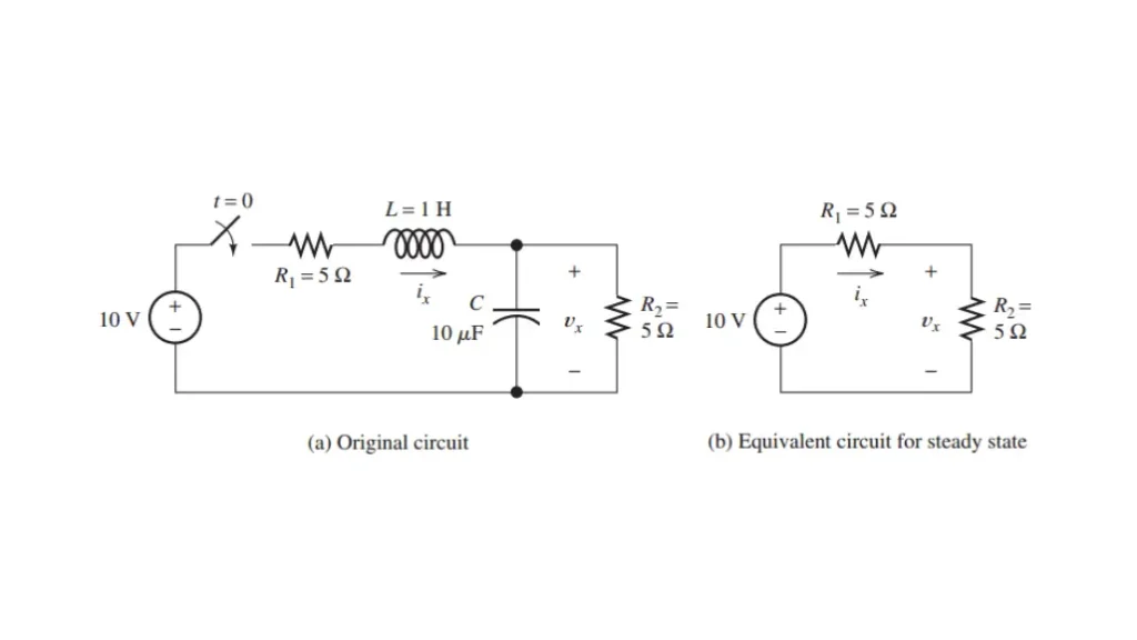
In a DC circuit, a capacitor acts as an open circuit in steady-state. This means that once the capacitor is fully charged, no current flows through it, and the voltage across it remains constant.
Therefore, the steady-state voltage across a capacitor in a DC circuit is equal to the voltage of the DC source connected to it.
Mathematical Representation
For a simple RC circuit with a DC voltage source (V₀), a resistor (R), and a capacitor (C) connected in series, the voltage across the capacitor (Vc) as a function of time (t) is given by:
Vc(t) = V₀(1 - e^(-t/RC))
As time approaches infinity (t → ∞), the exponential term e^(-t/RC) approaches zero. Thus, the steady-state voltage (Vc(∞)) becomes:
Vc(∞) = V₀
Visual Representation
As you can see from the graph of the voltage across the capacitor as a function of time, the voltage asymptotically approaches the source voltage V₀.
In essence, the steady-state voltage across a capacitor in a DC circuit is determined by the DC source voltage and the circuit configuration.
Note: In AC circuits, the behavior of capacitors is more complex, and the steady-state voltage can vary depending on the frequency of the AC signal and the circuit configuration.
Maximum Voltage Across a Capacitor Formula
The maximum voltage across a capacitor is determined by its breakdown voltage. This is the maximum voltage that the capacitor can withstand before its dielectric material breaks down and the capacitor fails.
It’s crucial not to exceed this voltage rating, as it can lead to catastrophic failure and potential safety hazards.
You can find the maximum voltage rating on the capacitor’s datasheet or marking. It’s typically labeled as a voltage value, such as “10V,” “50V,” or “100V.”
Important Note:
While the formula Q = CV relates the charge, capacitance, and voltage of a capacitor, it doesn’t directly determine the maximum voltage. The maximum voltage is a property of the capacitor’s dielectric material and its physical construction.
To summarize:
- Maximum voltage is a property of the capacitor itself, determined by its dielectric material and physical construction.
- It’s crucial to stay within the specified voltage rating to avoid damage.
- The formula Q = CV relates charge, capacitance, and voltage, but it doesn’t directly determine the maximum voltage.
Always refer to the capacitor’s datasheet for accurate information about its maximum voltage rating.
How to Measure Voltage Across a Capacitor With an Oscilloscope
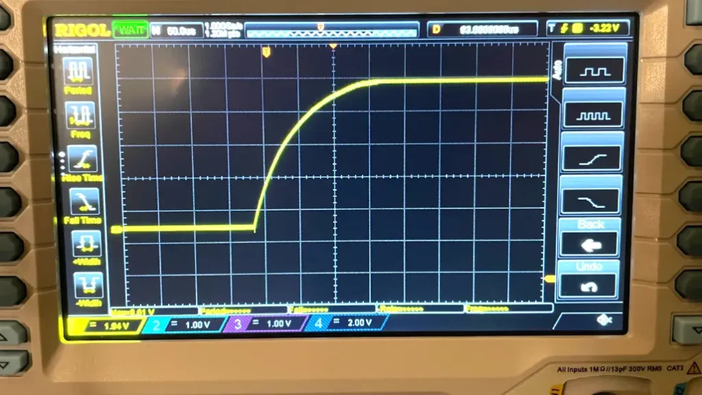
Setting Up Your Oscilloscope
Connect the Probes:
- Connect the two oscilloscope probes to the two terminals of the capacitor.
- Ensure the ground clips of the probes are connected to a common ground point in your circuit.
Adjust the Timebase:
- Set the timebase to an appropriate value to capture the voltage waveform across the capacitor.
- For slower changes, a longer timebase might be needed. For faster changes, a shorter timebase is suitable.
Adjust the Voltage Scale:
- Set the voltage scale to a suitable value to display the voltage range across the capacitor.
- You may need to adjust this as you experiment with different circuits and inputs.
Trigger the Oscilloscope:
- Set the trigger level and slope to capture the desired part of the waveform.
- This ensures that the oscilloscope starts capturing data at a specific point in the waveform.
Interpreting the Waveform
Once you’ve set up the oscilloscope, you’ll see a waveform on the screen. This waveform represents the voltage across the capacitor as a function of time.
DC Voltage:
- A straight horizontal line indicates a constant DC voltage across the capacitor.
- Measure the vertical distance between the line and the zero reference to determine the voltage.
AC Voltage:
- A sinusoidal or other periodic waveform indicates an AC voltage.
- Measure the peak-to-peak voltage or the RMS voltage, depending on the specific application.
- Use the oscilloscope’s measurement tools to accurately determine the voltage values.
Tips for Accurate Measurements:
- Probe Compensation: Ensure that your oscilloscope probes are properly compensated to avoid inaccurate readings.
- Grounding: Maintain a good ground connection to minimize noise and interference.
- Oscilloscope Settings: Experiment with different timebase and voltage scale settings to optimize the waveform display.
- Waveform Analysis: Use the oscilloscope’s built-in measurement tools to accurately measure voltage, frequency, and other parameters.
By following these steps and understanding the principles of oscilloscope operation, you can effectively measure the voltage across a capacitor and gain valuable insights into circuit behavior.
Charging and Discharging a Capacitor
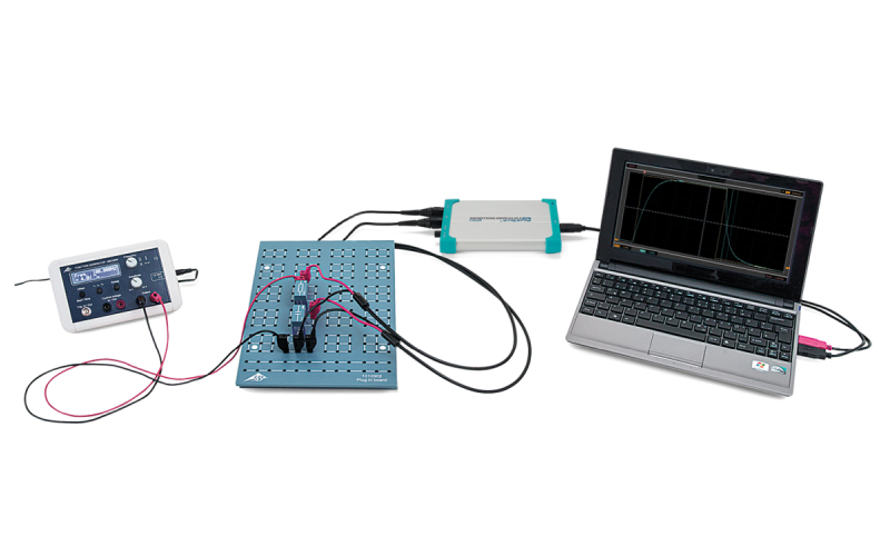
Now, let’s explore what happens during the charging and discharging processes of a capacitor.
Charging a Capacitor:
When a voltage source is connected across the capacitor, current flows into the capacitor, causing it to store charge. You will observe that as the charge accumulates, the voltage across the capacitor increases. The charging process does not happen instantaneously; it follows an exponential curve described by the time constant ($ \tau $), which is equal to $ R \times C $, where $ R $ is the resistance in the circuit.
As an engineer, you might find that understanding this time constant is crucial for designing circuits. It determines how quickly your capacitor charges, which can affect the overall performance of your electronic device.
Discharging a Capacitor:
When the voltage source is removed and the capacitor is connected to a load, it starts to release its stored energy. The voltage across the capacitor decreases exponentially as the charge flows out. The time constant also governs the discharging time.
You might be familiar with practical applications where this behavior is pivotal. For example, in timing circuits, capacitors are used to generate specific time delays. You need to understand how to control the voltage across these capacitors to achieve the desired timing.
The relationship between charging a capacitor, discharging it, and the voltage across it is fundamental to understanding capacitor behavior in electrical circuits.
Voltage Rating of Capacitors
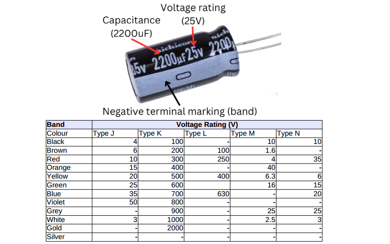
One of the critical aspects you must consider when selecting a capacitor is its voltage rating. The voltage rating indicates the maximum voltage the capacitor can handle without the risk of breakdown or failure.
As a capacitor supplier, we emphasize the importance of choosing a capacitor with a voltage rating higher than the maximum voltage it will encounter in the circuit. Failure to do so could result in catastrophic failure of the component, and potentially impact the entire circuit.
The voltage rating of a capacitor is a crucial parameter that must be carefully considered in any circuit design. By understanding the relationship between the voltage across the capacitor and its rated voltage, you can ensure the safe and reliable operation of your electronic devices.
Real-World Applications of Capacitors
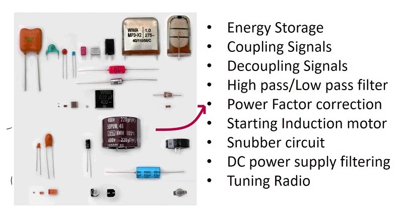
Understanding the voltage across capacitors plays a vital role in various applications, including:
Power Supply Filters: Capacitors are commonly used to smooth out voltage fluctuations in power supplies. By placing capacitors across the output, you can maintain a steady voltage level, which is essential for the reliable operation of electronic devices.
Timing Circuits: Those of you working on timing applications will appreciate how capacitors can create delays by charging and discharging at controlled rates. For instance, they are integral to RC (resistor-capacitor) timing circuits.
Energy Storage: Capacitors can serve as temporary energy storage devices. In applications like flash photography or pulsed lasers, capacitors can release stored energy almost instantaneously, providing a quick burst of power when needed.
Signal Coupling and Decoupling: Capacitors are used to couple AC signals between different stages of a circuit while blocking DC voltages. They also decouple noise in power supply lines, improving the overall performance of electronic devices.
Factors Affecting Voltage Across Capacitor
Several factors can influence the voltage across capacitor, and understanding them is key to designing robust circuits:
Capacitance Value: Different capacitors have different capacitance values, which affects the amount of charge they can store at a given voltage. You’ll often find that higher capacitance allows for more charge storage, but size and cost also increase.
Voltage Source Variations: In practical circuits, voltage sources may not always provide a stable output. Fluctuations can affect the voltage across capacitors, necessitating careful design considerations.
Temperature: The performance of capacitors can vary with temperature changes. Understanding how temperature affects capacitance and leakage current is crucial, especially in applications exposed to varying environmental conditions.
The Importance of Proper Circuit Design
As you design circuits involving capacitors, it’s essential to consider their placement and interaction with other components.
Parallel vs. Series Configuration: Capacitors can be connected in parallel or series to achieve desired values. In parallel, capacitance adds up, allowing for more charge storage; in series, the total capacitance decreases, which can limit performance.
Circuit Protection: It’s vital to include protective components such as diodes that prevent reverse polarity, especially when capacitors are charged. This can help avoid damage to sensitive parts.
The significance of Voltage Across Capacitor is also very important.
Common Mistakes to Avoid
When working with capacitors and their voltage characteristics, keep these common mistakes in mind:
Ignoring Voltage Ratings: It’s critical to choose capacitors with appropriate voltage ratings. Never underestimate the importance of this factor.
Assuming Instantaneous Charge/Discharge: Remember that capacitors do not charge or discharge instantaneously. Always account for the time constant in your designs.
Overlooking Leakage Current: Capacitors can leak current over time, affecting their performance. Make sure to factor in leakage when calculating the effective voltage across capacitor them in long-term applications.
FAQ
How Does a Capacitor Charge and Discharge?
Capacitors charge and discharge through the movement of electrical charge. This process is not instantaneous and follows an exponential curve characterized by the time constant $ \tau $, defined as $ \tau = R \times C $, where $ R $ is the resistance in the circuit.Charging: When connected to a voltage source, current flows into the capacitor, and the voltage across it rises until it equals the source voltage.
Discharging: Once disconnected from the source and connected to a load, the stored energy is released, and the voltage drops exponentially.
What Is the Importance of Voltage Rating in Capacitors?
The voltage rating of a capacitor is critical. It signifies the maximum voltage that can be applied across the capacitor without the risk of dielectric breakdown or failure.
As a rule of thumb, always choose a capacitor with a voltage rating at least 20% higher than the anticipated voltage to ensure reliability.
This is very important for Voltage Across Capacitor
What Are Common Applications of Capacitors in Circuits?
Power Supply Filtering: To smooth out voltage fluctuations and maintain a steady output.
Timing Circuits: For generating time delays in applications such as blinking LEDs or timing intervals in microcontroller circuits.
Energy Storage: In devices such as flash cameras where quick bursts of energy are needed.
Signal Coupling and Decoupling: To filter unwanted noise and transfer AC signals while blocking DC components.
These applications also require the rationality of Voltage Across Capacitor
Can I Use Different Types of Capacitors Interchangeably?
While it may be tempting to substitute one type of capacitor for another, it is important to consider their different characteristics, such as ESR (Equivalent Series Resistance), voltage ratings, capacitance, size, and temperature stability. Using the wrong type of capacitor can lead to inefficiency, noise, or even circuit damage.
How Can I Measure Voltage Across a Capacitor?
Use a Multimeter: Set the multimeter to the appropriate voltage range, and connect the probes across the capacitor. Ensure the circuit is de-energized before working with capacitors, especially high-value ones.
Observe Charging/Discharging Curves: If you’re measuring in an active circuit, use an oscilloscope to visualize the voltage change over time as the capacitor charges or discharges.
Conclusion
In conclusion, understanding the voltage across a capacitor is vital for anyone involved in electronics. Whether you’re designing circuits or simply working on projects, knowing how capacitors store and release energy will enhance your grasp of electronic principles.
As a capacitor supplier, we are dedicated to providing the best components for your needs and ensuring that you have the knowledge to use them effectively. Always remember the importance of selecting the right capacitors, considering their voltage ratings, and understanding their behavior in circuits.