In the realm of electronics, there exists a special circuit that bridges the gap between the theoretical world of calculus and the practical applications of electrical engineering. This marvelous creation is known as the op-amp integrator circuit.
But how exactly does this ingenious circuit achieve this mathematical feat? Let’s delve into the intricacies of its operation and explore the fascinating applications it unlocks.
What is an Integrator Circuit Op Amp
An integrator circuit op-amp is a circuit that utilizes an operational amplifier (op-amp) to perform the mathematical function of integration on a voltage signal. In simpler terms, it takes a voltage that changes over time (input signal) and outputs a voltage proportional to the total area under the curve of that changing voltage.
Here’s a breakdown of the key components:
- Operational Amplifier (Op-Amp): This versatile chip acts as the amplifier for the circuit. It takes a small difference in voltage between its two inputs and amplifies it into a much larger output voltage.
- Capacitor: This passive component acts like a temporary storage unit for electrical charge. The amount of charge it stores depends on the voltage applied to it.
Integrator Circuit Using Op Amp 741
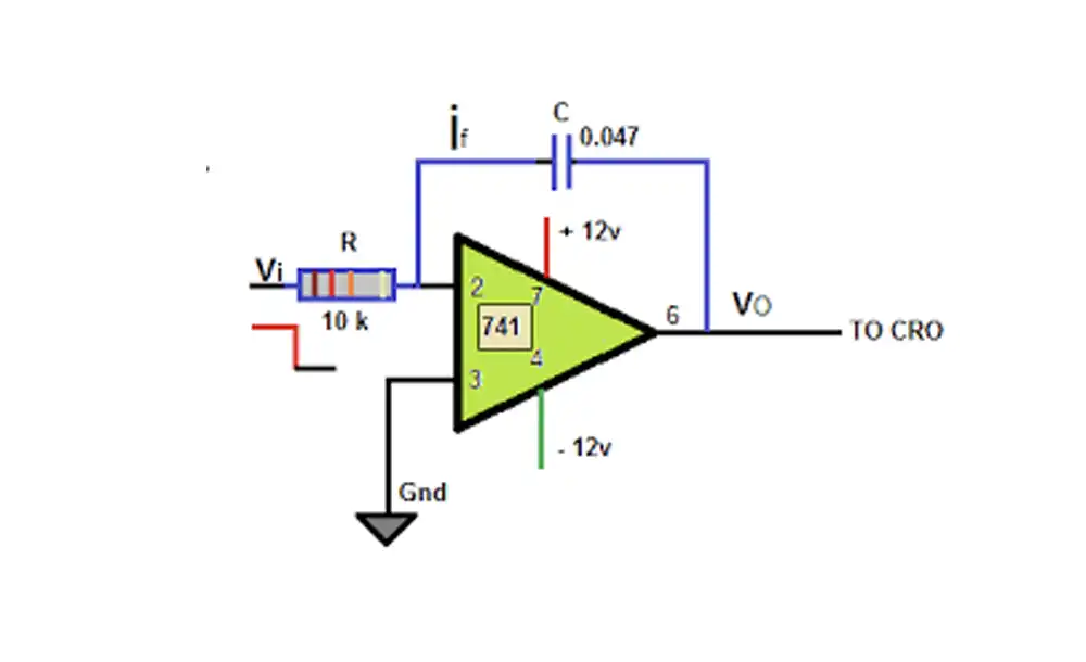
The venerable 741 op-amp can definitely be used to create an integrator circuit.
Here’s a breakdown of what you’ll need and how it works:
Components:
- Op-Amp (IC 741)
- Resistor (Rin)
- Capacitor (C)
Circuit Design:
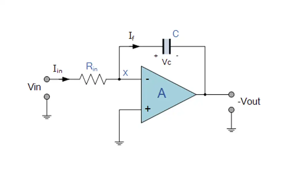
This is a basic inverting integrator configuration. Here’s how to connect the components:
- Input Signal: Connect your input voltage signal (Vin) to the inverting input terminal (pin 2) of the 741 op-amp.
- Capacitor: Connect one terminal of the capacitor (C) to the inverting input (pin 2) as well. The other terminal of the capacitor connects to ground.
- Resistor: Connect one terminal of the resistor (Rin) to the inverting input (pin 2) and the non-inverting input (pin 3) of the op-amp. The other terminal of the resistor connects to positive voltage (+Vcc) from your power supply.
- Output: The output voltage (Vout) is available at pin 6 of the 741 op-amp.
How it Works:
- The input voltage (Vin) applied to the inverting input creates a voltage difference between it and the virtual ground (assumed 0V) at the non-inverting input.
- This voltage difference drives current through the resistor (Rin) and into the capacitor (C).
- Positive Vin: Current flows into the capacitor, charging it up (voltage across C increases).
- Negative Vin: Current flows out of the capacitor, discharging it (voltage across C decreases).
- The op-amp continuously adjusts its output voltage (Vout) to create a current through the capacitor that opposes the current flowing through Rin. This opposing current effectively “cancels out” the voltage difference at the inverting input.
- Over time, the capacitor integrates the input voltage (Vin). The voltage across the capacitor (Vc) gradually reflects the integral of Vin.
- The required current to maintain the virtual ground at the inverting input is proportional to the voltage across the capacitor (Vc).
- The op-amp’s high gain amplifies this current to a much larger output voltage (Vout) that represents the integral of the input voltage.
Important Notes:
- This is an inverting integrator, meaning the output voltage (Vout) has the opposite polarity of the integral of the input voltage (if Vin increases, Vout will decrease and vice versa).
- The 741 op-amp has limitations like finite bandwidth, input offset voltage, and slew rate. These can affect the accuracy and performance of the integrator circuit, especially at high frequencies or with large input signals.
- Carefully choose the values of Rin and C based on your desired time constant (the time it takes for the output to reach 63% of its final value) and the frequency range of your input signal.
How Does Integrator Circuit Op Amp Work
The op-amp integrator circuit performs the mathematical function of integration on a voltage signal. Here’s a deeper dive into how it achieves this:
Key Players:
- Operational Amplifier (Op-Amp): This integrated circuit acts as a high-gain differential amplifier. It amplifies the voltage difference between its two inputs (inverting and non-inverting) by a large factor.
- Capacitor: This passive component stores electrical charge based on the applied voltage. The higher the voltage, the more charge it holds.
The Integration Process:
Input Signal: A voltage signal (Vin) is applied to the inverting input terminal of the op-amp.
Virtual Ground: The op-amp strives to maintain a virtual ground at its inverting input (inverting input voltage ≈ 0V). It achieves this by adjusting its output voltage (Vout).
Current Flow and Capacitor Charge/Discharge: The difference between Vin and the virtual ground (assumed 0V) creates a voltage difference across the input resistor (Rin). This drives current through Rin and into the capacitor (C). The direction of current flow depends on the polarity of Vin.
- Positive Vin: Current flows into the capacitor, charging it up (voltage across C increases).
- Negative Vin: Current flows out of the capacitor, discharging it (voltage across C decreases).
Op-Amp’s Response: Since the op-amp wants to maintain a virtual ground, it adjusts Vout to create a current through the feedback path (often just the capacitor) that opposes the current flowing through Rin. This opposing current effectively “cancels out” the voltage difference at the inverting input.
Integration Over Time: This continuous battle between the input voltage and the capacitor’s charge unfolds over time. As Vin changes, the capacitor charges or discharges accordingly. The voltage across the capacitor (Vc) gradually integrates the input voltage (Vin) over time.
Output Voltage (Vout): The required current to maintain the virtual ground at the inverting input is proportional to the voltage across the capacitor (Vc) due to the relationship between current and voltage in a capacitor (I = C * dVc/dt). Since the op-amp has a high gain, the output voltage (Vout) is amplified to a much larger value that reflects the integral of the input voltage.
In essence, the op-amp integrator uses the capacitor’s charging/discharging behavior to “remember” the history of the input voltage and reflects that history in its output voltage.
Here are some additional points to consider:
- The integrator circuit is typically used in an inverting configuration, meaning the output voltage has the opposite polarity of the integral of the input voltage.
- Real-world integrators have limitations, such as op-amp saturation voltage and input bias current. These can affect the accuracy and functionality of the circuit, requiring careful design considerations.
I hope this explanation provides a clearer picture of how the op-amp integrator circuit works!
Integrator Op Amp Circuit Example
Components:
- Operational Amplifier (Op-Amp)
- Resistor (Rin)
- Capacitor (C)
Explanation:
- The input voltage signal (Vin) is applied to the inverting input terminal of the op-amp.
- The capacitor (C) is connected between the inverting input and the ground.
- The resistor (Rin) is connected between the inverting input and the non-inverting input of the op-amp.
- The non-inverting input (usually) sits at a virtual ground (0V) due to the high gain of the op-amp.
Differential Integrator Op Amp Circuit
In the world of op-amp circuits, there isn’t a separate circuit specifically called a “differential integrator.” However, there are two possibilities when you encounter this term:
Standard Integrator with a Differential Input:
A standard inverting integrator circuit, like the one we discussed previously, can be used with a differential input signal. This means instead of a single voltage signal applied to the inverting input, you might have two separate voltage signals (Vin1 and Vin2) applied differentially.
Here’s how it works:
- Differential Input: Two voltage signals (Vin1 and Vin2) are applied to the inverting input terminal. These signals could be connected directly to the inverting input or through individual resistors depending on the desired weighting of each signal.
- Virtual Ground: The op-amp still strives to maintain a virtual ground at its inverting input.
- Combined Integration: The current flow through the feedback resistor (Rin) and into the capacitor (C) is now based on the combined voltage difference between the two input signals (Vin1 – Vin2).
- Output Voltage: The output voltage (Vout) will be the amplified integral of the difference between the two input signals.
Combination of Integrator and Differential Amplifier:
Another possibility is that you might be referring to a circuit that combines the functionality of both an integrator and a differential amplifier. This could involve using two separate op-amps, one configured as a differential amplifier and the other as an integrator.
Here’s a simplified explanation of this approach:
- Differential Amplifier Stage: The first stage uses an op-amp as a differential amplifier to amplify the difference between the two input signals (Vin1 and Vin2).
- Integrator Stage: The output of the differential amplifier stage is then fed into a second op-amp configured as an integrator. This integrator then performs the integration on the amplified difference signal.
Important Note:
It’s important to understand the specific context when encountering the term “differential integrator” in op-amp circuits. For most applications, using a standard integrator with a differential input or the two-stage approach described above would achieve the desired functionality.sharemore_vert
Conclusion
Ready to Unlock the Power of Integration with Our High-Performance Op-Amp Circuits?
Do you require a custom integrator circuit op-amp to bring your project to life?
At weishielectronics, we specialize in designing and manufacturing top-of-the-line op-amp circuits, including integrator circuits tailored to your specific needs.
Our team of experienced engineers possesses in-depth knowledge of integrator circuit functionality and can create a solution that seamlessly integrates with your existing system.
Here’s what sets us apart:
- Custom Design: We don’t offer a one-size-fits-all solution. We meticulously design integrator circuits based on your application’s unique requirements, ensuring optimal performance.
- High-Quality Components: We utilize premium op-amps and capacitors to guarantee reliable operation and accurate integration.
- Expert Support: Our team is readily available to answer your questions and provide ongoing technical support throughout the process.
Get a Free Quote Today!
Whether you have a clear vision or need guidance on the best approach for your project, contact us today. We’ll discuss your needs, provide expert recommendations, and offer a competitive quote for your custom integrator circuit op-amp.
Don’t wait! Fill out our online form or call us at [Phone Number] to transform your project into reality.
Together, let’s integrate success!
P.S. We also offer a comprehensive library of resources on integrator circuits, including application guides and design tutorials. Visit our website at [Your Company Website] to learn more!