Testing a diode is a fundamental skill for anyone involved in electronics, whether a hobbyist, student, or professional. Diodes are essential components in many electronic circuits, serving as gatekeepers that allow current to flow in one direction while blocking it in the opposite direction.
Understanding how to test a diode ensures that circuits function correctly and helps diagnose issues in malfunctioning electronics. This guide offers a clear, step-by-step approach to testing diodes, making it accessible for beginners and a useful refresher for experienced technicians.
What Is A Diode?
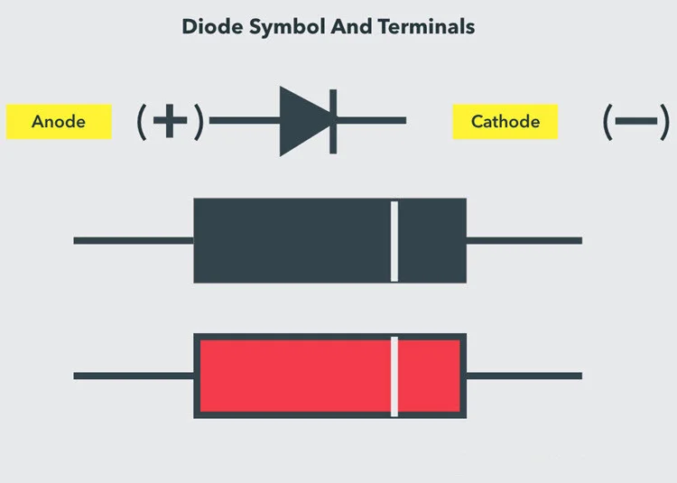
If you want to understand what a diode is, let’s dive into it. A diode, essentially, is a semiconductor device that allows current to flow in one direction only. It’s like a gatekeeper for electricity, permitting its passage in one direction while blocking it in the other. In electronic circuits, diodes serve various purposes, such as rectifying alternating current (AC) to direct current (DC), regulating voltage, and protecting circuits from reverse voltage.
Understanding the role of diodes is crucial in electronics, as they form the foundation for many electronic devices and circuits. So, to sum up, a diode is a semiconductor component that acts as a one-way street for electrical current, offering essential functionality in electronic systems.
How To Test A Diode With A Digital Multimeter?
When you’re testing a diode, the Diode Test Mode offers the most reliable approach by leveraging the diode’s inherent characteristics. Through this method, you place the diode in forward bias and gauge the voltage drop across it, utilizing a Multimeter. In forward bias, a properly functioning diode will facilitate current flow and exhibit a voltage drop.
Transitioning to the Resistance Mode Test, you measure both the forward and reverse bias resistances of the diode. For an optimal diode, the forward bias resistance typically ranges from a few hundred Ohms to several Kilo Ohms, while the reverse bias resistance should register as very high (often denoted as OL – open loop in a multimeter).
Diode Mode Testing Procedure
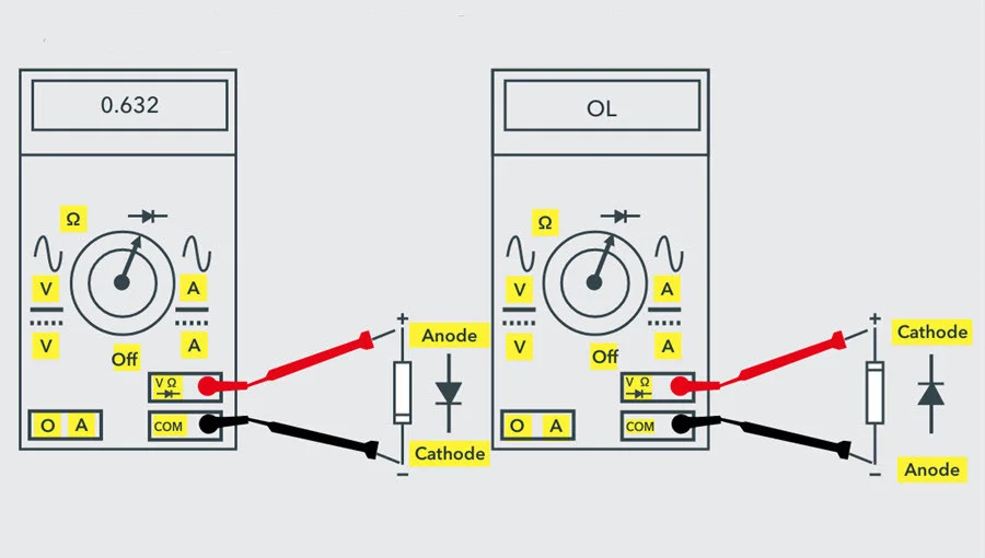
To pinpoint the anode and cathode terminals of the diode, first ensure your Digital Multimeter (DMM) is set to diode-checking mode. Rotate the central knob until you see the diode symbol. In this mode, the DMM can supply around 2mA of current between the test leads.
Next, connect the red probe of the multimeter to the anode and the black probe to the cathode. This configuration establishes forward biasing for the diode. Check the reading on the multimeter’s display. A healthy Silicon Diode should display a voltage value between 0.6 to 0.7, while for Germanium Diodes, it should be between 0.25 to 0.3.
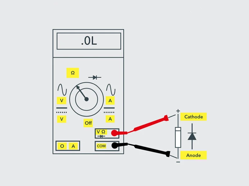
Now, reverse the terminals of the meter, with the red probe to the cathode and the black to the anode. This represents the reverse-biased condition of the diode, where no current should flow. A healthy diode should show OL or 1 (indicating an open circuit) on the meter.
If the meter displays values not consistent with these conditions, it suggests a defective diode. An open diode acts like an open switch in both forward and reverse biases, resulting in no current flow. Hence, the meter will indicate OL (or 1) in both bias conditions.
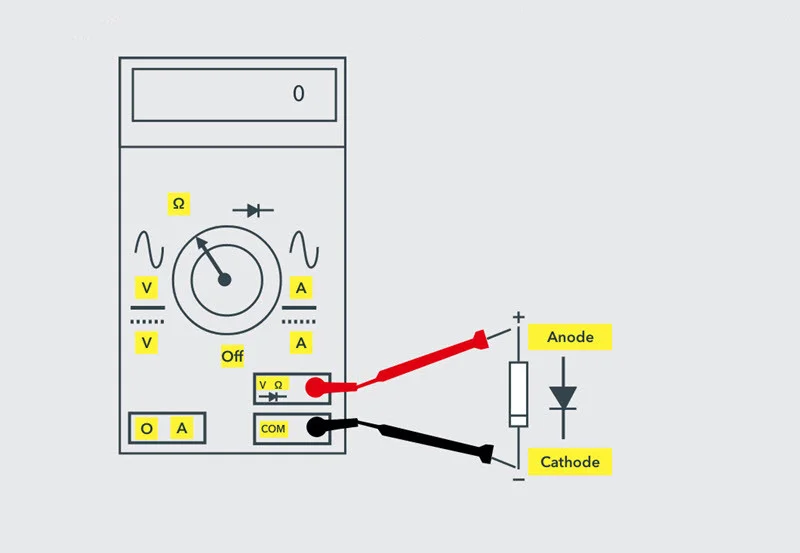
Conversely, a shorted diode behaves as a closed switch, allowing current flow regardless of bias, with a voltage drop between 0V to 0.4V. Consequently, the multimeter may show a zero voltage value, although in some instances, it may display minimal voltage due to the voltage drop across the diode.
Ohmmeter (Resistance) Mode Testing Procedure
Just like the Diode Test method, the Resistance Mode offers another straightforward approach to assess the diode’s condition, determining if it’s good, shorted, or open. Start by identifying the terminals of the diode, namely the anode and cathode.
Set your Digital Multimeter (DMM) to resistance or ohmmeter mode by adjusting the central knob or selector to where the ohm symbol or resistor values are displayed. For forward bias testing, keep the selector in low resistance mode (perhaps 1K ohm), while for reverse bias testing, switch to high resistance mode (100K ohm).
Connect the red probe to the anode and the black probe to the cathode. This configuration establishes forward biasing for the diode, where the diode’s resistance is extremely low.
Check the meter display. If it shows a moderately low value, such as a few tens of ohms, the diode is likely not in good condition. However, if the resistance reading falls within a range from a few hundred ohms to several kilo ohms, the diode is functioning correctly.
Now, switch the terminals of the multimeter so that the anode connects to the black probe and the cathode to the red probe, effectively putting the diode into a reverse-biased state.
When the meter displays a very high resistance value or OL, it indicates that the diode is in good working order since, in reverse-biased situations, the diode should exhibit very high resistance.
From this, it becomes evident that for the diode to function correctly, the DMM should register low resistance in forward bias and very high resistance or OL in reverse bias.
If the meter shows very high resistance or OL in both forward and reverse biases, the diode is considered open. Conversely, if the meter indicates very low resistance in both directions, the diode is deemed shorted.
How To Test A Diode With An Analog Multimeter?
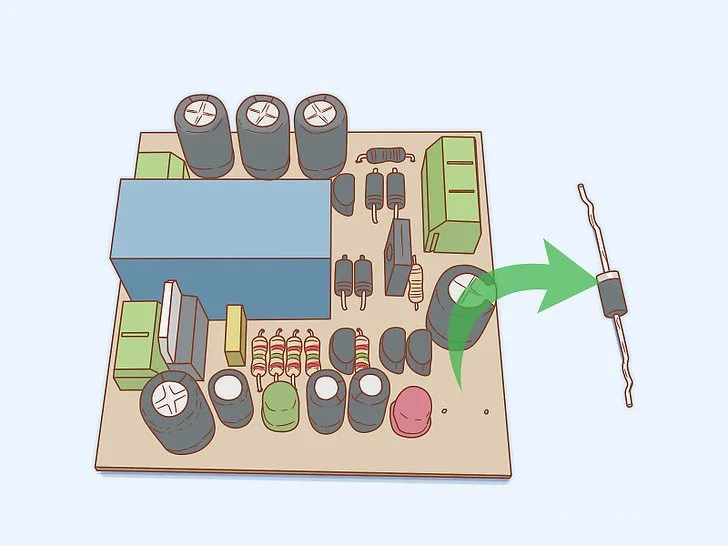
Turn off the diode’s power source. If you test a diode while it remains in a circuit, not only will it distort results, but you also face significant danger. To mitigate this risk, remove the diode entirely from the circuit or switch off the energy source, which could be an electrical outlet or battery. Additionally, discharge the capacitors to eliminate any excess voltage they hold, thus reducing the risk of experiencing an explosion or electric shock.
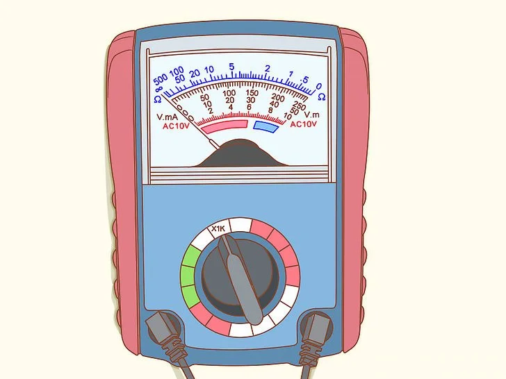
Adjust the selector switch to low resistance, typically around 1 KΩ. By setting the multimeter to low resistance, you enable controlled current flow through the diode without risking overload. The selector switch, located at the center of the multimeter, facilitates this adjustment.
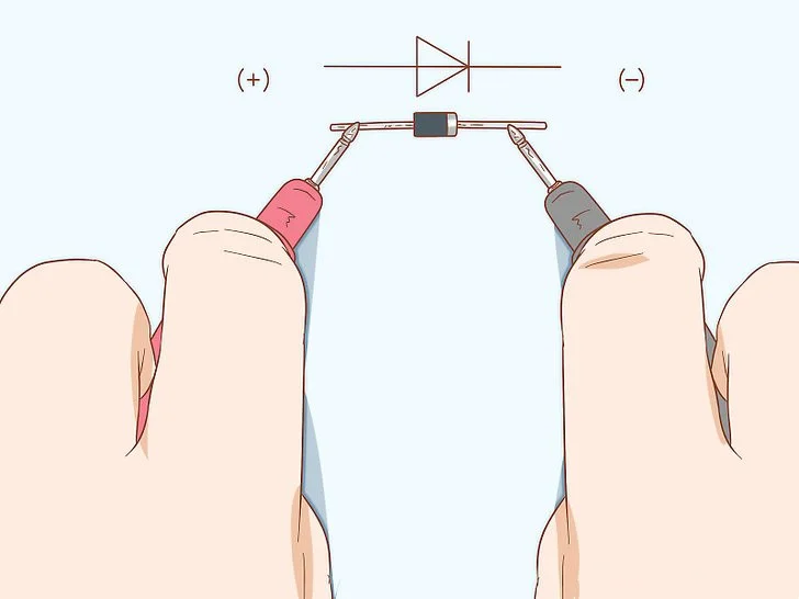
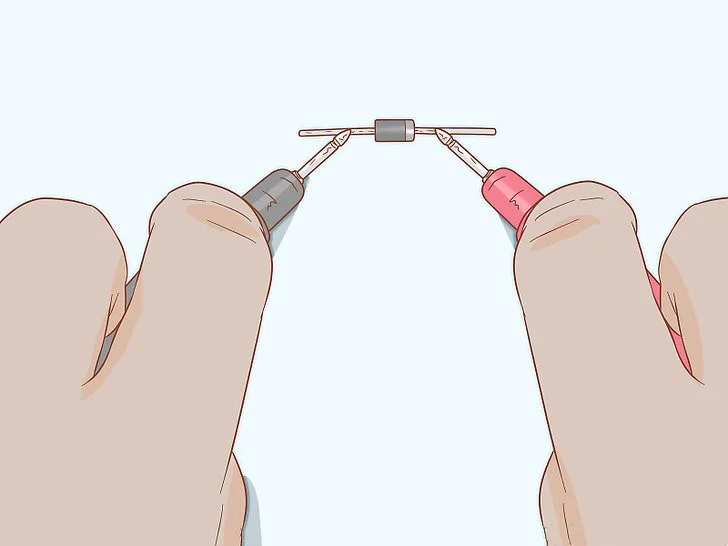
Place the red lead on the anode and the black lead on the cathode. The anode denotes the positive end, whereas the cathode signifies the negative end. This configuration forward-biases the diode, allowing current to flow through it. To easily distinguish between the cathode and anode, locate the silver stripe, indicating the cathode. The leads are equipped with mini alligator clips at the ends, which you will utilize to connect to the diode.
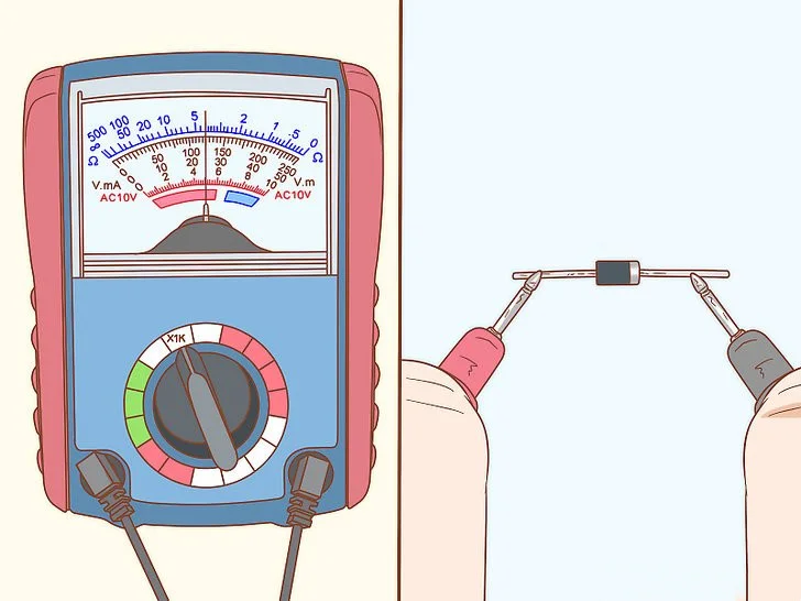
Examine the meter reading to assess the health of the diode. If your diode is forward-biased, a working diode will yield a meter reading ranging between 1 Ω and 100 Ω. Conversely, if the diode is reverse-biased, the meter should display infinite resistance, indicating an open diode. Any lower resistance reading for either type of diode signifies a shorted diode, necessitating replacement. In either scenario, it is advisable to replace your diode.
If you encounter no reading at all, ensure the leads are firmly clipped onto the diode. Verify the functionality of your leads by testing them with a brand-new battery. Switch the multimeter to voltage mode and attach the red clip to the positive end while connecting the black clip to the negative end. If the meter reading fails to correspond with the battery voltage, it indicates a requirement for new leads.
Switch the red lead to the cathode and the black lead to the anode. This action places the diode in a reverse-biased state, where no current flows through it. For optimal results, adjust the dial to high resistance, approximately 100 KΩ, before attaching the leads to their new positions. High resistance is essential in this context because reverse bias aims to impede or resist all current flow.
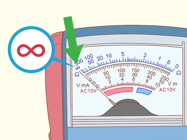
Seek a reading indicating an open loop (OL) or the infinity symbol. This indicates that the diode is functioning correctly. If you receive a low resistance reading, it indicates a faulty diode that requires replacement.
Replacing a diode can be as straightforward as exchanging standard batteries. However, you might need to perform minor soldering on the ends to affix it to the circuit.
How To Test LED Diode?
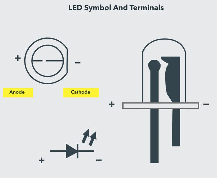
As mentioned earlier, it’s essential to identify the pins (terminals) of any diode before testing it. The terminals of an LED can be distinguished by the length of their leads: the longer lead is the anode, and the shorter one is the cathode. Alternatively, you can utilize the surface structure, where a flat surface denotes the cathode, while the other side is the anode.
Now, let’s proceed to the steps for testing an LED using a digital multimeter.
First, locate the anode and cathode terminals of the LED. Next, set the multimeter selector/knob to diode mode. Then, connect the meter probes to the LED in a forward-biased configuration. If the LED functions correctly, it will emit light; otherwise, it is defective. Note that reverse-biased testing is not feasible with LEDs since they do not operate under reverse-biased conditions.
How To Test A Zener Diode?
Testing a Zener diode requires additional circuitry compared to testing a regular diode. This is because the Zener diode conducts in a reverse-biased condition only if the applied reverse voltage exceeds the Zener breakdown voltage.
Begin by identifying the anode and cathode terminals of the Zener diode, a process similar to that of a standard PN diode, typically using a marking. Next, set up the test circuit as illustrated in the figure provided. Set the multimeter knob to voltage mode, then connect the meter probes across the Zener diode according to the figure.
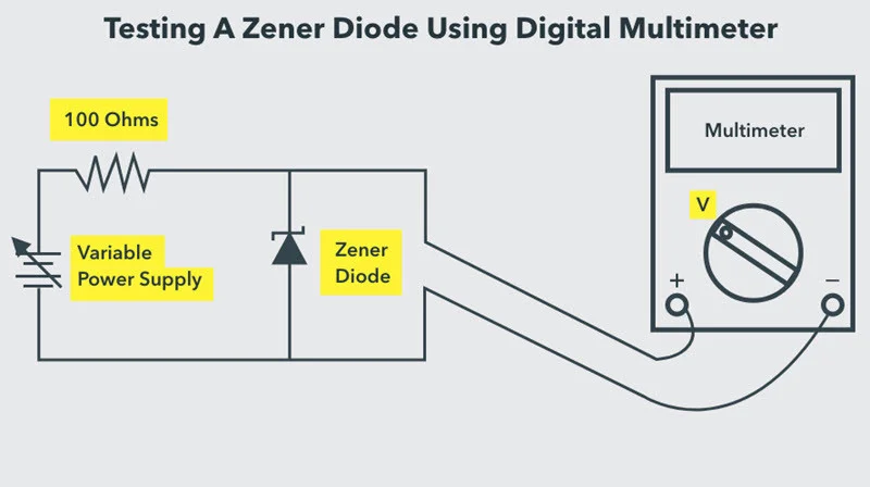
Gradually increase the input supply to the diode and observe the voltage displayed on the meter. The meter reading should increase as the variable supply is increased until it reaches the breakdown voltage of the diode. Beyond this point, the meter should indicate a constant voltage regardless of any further increase in the input variable supply. If this occurs, the Zener diode is deemed healthy; otherwise, it is defective.
For example, if we apply a 12V input to a Zener diode with a breakdown voltage of 6V from a battery via a resistor, the multimeter should display a reading approximately equal to 6V if the Zener diode is functioning correctly.
Conclusion
In summary, testing a diode is crucial for troubleshooting and maintaining electronics. By following proper procedures and using the right tools, individuals can accurately assess diode health. This involves identifying diode terminals, employing a digital multimeter in the correct mode, and observing specific behaviors and readings.
Prompt replacement of defective diodes ensures circuit functionality. Mastering diode testing empowers individuals to resolve electrical issues, enhancing system reliability and performance through diligent practice.