Testing a circuit breaker is an essential aspect of maintaining a safe and efficient electrical system in your home or building.
A circuit breaker serves as a crucial line of defense against electrical overloads and faults, preventing potential hazards such as fires and damage to appliances. Conducting regular tests on circuit breakers helps ensure they are functioning properly and can effectively interrupt the flow of electricity when needed.
In this guide, we will explore various methods and techniques for testing a circuit breaker, providing you with the knowledge and tools necessary to assess the integrity of your electrical system and maintain its safety and reliability.
What Is a Circuit Breaker
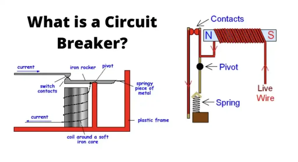
A circuit breaker is an essential component of an electrical system, designed to protect circuits from damage caused by overloads or short circuits. It functions as an automatic switch that interrupts the flow of electricity when a fault is detected, thereby preventing potential hazards such as fires or damage to appliances and wiring.
Key Functions of a Circuit Breaker:
- Protection: Circuit breakers safeguard electrical circuits by cutting off the power when an abnormal current is detected, preventing overheating and potential fires.
- Control: They allow for the manual switching off of electrical circuits for maintenance or emergency purposes.
- Isolation: Circuit breakers help isolate faulty sections of an electrical system, making it easier to troubleshoot and repair issues.
Types of Circuit Breakers:
- Standard Breakers: Commonly used in homes and buildings, they protect against overloads and short circuits.
- Ground Fault Circuit Interrupters (GFCIs): These are designed to protect against ground faults, which occur when electricity escapes its intended path to the ground.
- Arc Fault Circuit Interrupters (AFCIs): AFCIs protect against arc faults, which can cause fires by detecting unintended electrical arcs and disconnecting the power.
How Circuit Breakers Work:
When electrical current exceeds a breaker’s rated capacity, it triggers an internal mechanism that opens the circuit, stopping the flow of electricity. This can happen due to various reasons, such as too many devices plugged into one circuit (overload) or a short circuit caused by faulty wiring.
Importance of Circuit Breakers:
- Safety: They prevent electrical fires and protect people from electric shocks.
- Device Protection: By stopping excessive currents, circuit breakers protect appliances and devices from damage.
- System Longevity: They contribute to the long-term health of an electrical system by preventing damage to wiring and other components.
A circuit breaker is a critical safety device in any electrical system, providing protection, control, and isolation to ensure safe and efficient operation.
How to Test a Circuit Breaker With a Multimeter
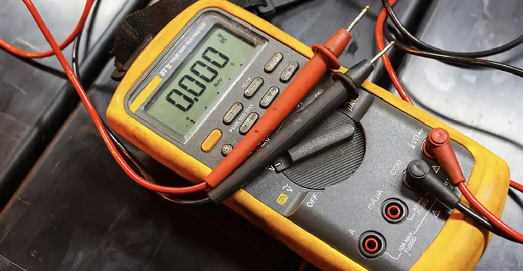
Testing a circuit breaker with a multimeter is a straightforward process that involves checking for continuity and measuring voltage. Here’s a detailed, step-by-step guide on how to test a circuit breaker with a multimeter:
What You’ll Need:
- Multimeter: Ensure it’s set to measure voltage and continuity.
- Safety Gear: Wear insulated gloves and safety goggles.
- Screwdriver: To remove the breaker panel cover.
Step-by-Step Instructions about How to Test a Circuit Breaker With Multimeter
Turn Off the Main Power:
- Explanation: For safety, always turn off the main power supply to the breaker panel. This prevents any risk of electric shock while you’re working.
- How to: Locate the main breaker at the top of the panel and switch it to the “Off” position.
Remove the Breaker Panel Cover:
- Explanation: Removing the cover gives you access to the individual breakers inside the panel.
- How to: Use a screwdriver to unscrew the panel cover. Set the screws aside in a safe place and carefully remove the cover.
Set the Multimeter to Voltage Testing:
- Explanation: To check if the breaker is receiving power, you need to measure the voltage.
- How to: Turn the multimeter dial to the AC voltage setting (usually indicated by a “V” with a wavy line).
Test the Voltage:
- Explanation: This step checks if the breaker is getting the correct voltage from the main power line.
- How to: Place one probe of the multimeter on the terminal screw of the breaker (where the wire is connected) and the other probe on a grounded metal part of the panel. The multimeter should read around 120 volts for a single-pole breaker and around 240 volts for a double-pole breaker.
Set the Multimeter to Continuity Testing:
- Explanation: Checking continuity ensures that the breaker is allowing electrical flow through it when in the “On” position.
- How to: Turn the multimeter dial to the continuity setting, usually indicated by a symbol resembling a sound wave or diode.
Remove the Wires from the Breaker:
- Explanation: Disconnecting the wires allows you to test the breaker without interference from the circuit.
- How to: Use a screwdriver to loosen the terminal screws and carefully pull the wires out.
Test for Continuity:
- Explanation: This step verifies that the breaker is capable of passing current when switched on.
- How to: Touch one multimeter probe to the breaker’s terminal screw and the other probe to the breaker’s load terminal. If the breaker is functioning correctly, the multimeter will beep or show a low resistance value, indicating continuity. No beep or an infinite reading means the breaker is faulty.
Reattach the Wires:
- Explanation: Once testing is complete, you need to reconnect the wires to the breaker.
- How to: Insert the wires back into their respective terminals and tighten the screws securely.
Replace the Breaker Panel Cover:
- Explanation: To ensure safety and proper functioning, put the panel cover back in place.
- How to: Align the cover over the panel and screw it back on using the screwdriver.
Turn the Main Power Back On:
- Explanation: Restoring power to the panel allows you to check if the breaker functions under normal conditions.
- How to: Switch the main breaker back to the “On” position.
Test the Circuit:
- Explanation: Ensure that the circuit controlled by the breaker is working correctly.
- How to: Turn on the devices or appliances connected to the circuit and check if they operate without tripping the breaker.
Safety Tips:
- Always double-check that the main power is off before beginning any work.
- Wear appropriate safety gear, such as insulated gloves and goggles.
- If you’re unsure or uncomfortable with any part of the process, consult a professional electrician.
Testing a circuit breaker with a multimeter helps ensure your electrical system is safe and functional. Following these detailed steps can help you diagnose issues and maintain the integrity of your electrical circuits.
Voltage Testing vs Resistance Testing for Testing a Circuit Breaker
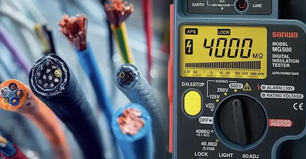
Voltage testing and resistance testing are two common methods used to test circuit breakers, each serving a different purpose in diagnosing electrical issues. Here’s a comparison between the two:
Voltage Testing:
- Purpose: Voltage testing is used to determine if electrical power is present at a specific point in the circuit.
- Method: A multimeter is set to measure voltage (typically AC voltage) and the probes are placed across the circuit or component being tested.
- Results: If voltage is present, the multimeter will display a reading indicating the voltage level. This confirms that electrical power is reaching the circuit breaker.
- Use Cases: Voltage testing is useful for verifying if power is reaching the circuit breaker, helping to identify issues such as a lack of power supply or a faulty connection.
Resistance Testing:
- Purpose: Resistance testing, also known as continuity testing, checks if electrical continuity exists between two points in a circuit.
- Method: The multimeter is set to measure resistance or continuity, and the probes are placed across the circuit or component being tested.
- Results: If continuity exists, the multimeter will typically emit a beep or display a low resistance value. This indicates that electrical current can flow freely between the tested points.
- Use Cases: Resistance testing is helpful for verifying the integrity of electrical connections, such as confirming that a circuit breaker allows current to pass through when in the “On” position. It can also identify breaks or faults in wiring.
Comparison:
- Purpose: Voltage testing checks for the presence of electrical power, while resistance testing verifies the continuity of electrical flow.
- Information Provided: Voltage testing provides information about the presence and level of electrical power, while resistance testing confirms the integrity of electrical connections.
- Application: Voltage testing is typically used to diagnose power supply issues, whereas resistance testing is more focused on assessing the condition of electrical pathways and components.
Voltage testing and resistance testing are complementary methods used in electrical troubleshooting. While voltage testing confirms the presence of power, resistance testing ensures that electrical pathways are intact and functional. Depending on the nature of the electrical issue, one or both of these tests may be necessary to diagnose and resolve problems effectively.
| Aspect | Voltage Testing | Resistance Testing |
|---|---|---|
| Purpose | Determine if electrical power is present | Verify continuity of electrical flow |
| Method | Multimeter set to measure voltage (AC/DC) | Multimeter set to measure resistance/continuity |
| Results | Displays voltage level if power is present | Emits beep or shows low resistance if continuity exists |
| Information Provided | Presence and level of electrical power | Integrity of electrical connections |
| Application | Diagnose power supply issues | Assess condition of electrical pathways |
This table summarizes the key differences between voltage testing and resistance testing, highlighting their respective purposes, methods, results, and applications in electrical troubleshooting.
Conclusion
In conclusion, testing a circuit breaker is a crucial step in ensuring the safety and functionality of your electrical system. By employing methods such as voltage testing and resistance testing, you can identify issues such as power supply problems or faulty connections that may affect the performance of the circuit breaker.
Regular testing helps to detect potential issues early, allowing for timely repairs or replacements and preventing electrical hazards. Whether you’re a homeowner performing routine maintenance or a professional electrician diagnosing complex electrical issues, thorough testing of circuit breakers is essential for maintaining the integrity and reliability of your electrical system.