In electronics, capacitors are fundamental components that store electrical energy and release it when needed. Understanding how to connect a capacitor properly is crucial for ensuring the smooth functioning of electronic circuits.
This guide’ll delve into the intricacies of connecting capacitors, covering everything from basic concepts to practical applications.
What Are Capacitors?
Capacitors are electronic components used in circuits to store and release electrical energy. They consist of two conductive plates separated by an insulating material called a dielectric.
When a voltage is applied across the plates, one plate accumulates positive charge while the other accumulates negative charge, creating an electric field between them. This process allows capacitors to store energy in the form of an electric field.
Capacitors are commonly used in a variety of electronic devices and circuits for purposes such as filtering, smoothing power supplies, and timing. They come in various types and sizes, each suited for different applications.
Types of Capacitors
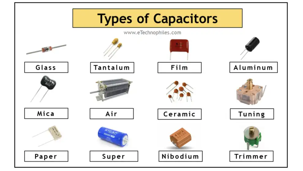
Capacitors come in various types, each designed to suit specific applications and requirements. Here are some common types of capacitors:
Electrolytic Capacitors: These capacitors use an electrolyte as the dielectric, allowing for high capacitance values in a small size. They are polarized, meaning they have a positive and negative terminal. Electrolytic capacitors are commonly used in power supply circuits and audio systems.
Ceramic Capacitors: Ceramic capacitors use ceramic materials as the dielectric. They are available in a wide range of capacitance values and are non-polarized, making them suitable for various applications, including decoupling and filtering in electronic circuits.
Film Capacitors: Film capacitors use a thin film of metal deposited on a non-conductive substrate as the dielectric. They offer high reliability, stability, and low losses, making them suitable for applications requiring precision and durability, such as timing circuits and audio equipment.
Tantalum Capacitors: Tantalum capacitors use tantalum metal as the anode and an electrolyte as the cathode. They offer high capacitance values in a small size and are commonly used in portable electronics and telecommunications devices.
Variable Capacitors: Unlike fixed capacitors, variable capacitors have adjustable capacitance values. They consist of two sets of plates, with one set movable to change the overlap area, thus altering the capacitance. Variable capacitors are used in tuning circuits and frequency-adjusting applications.
Each type of capacitor has its unique characteristics and advantages, allowing engineers to select the most suitable component for their specific design requirements. Understanding the differences between these types is crucial for effective circuit design and optimization.
Symptoms and Signs of Capacitors
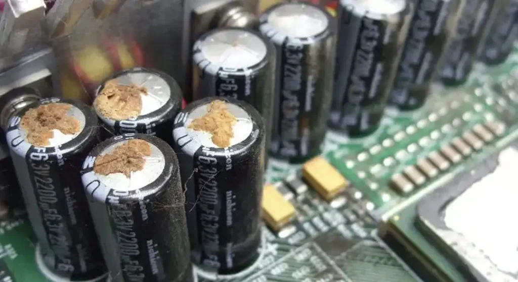
Identifying symptoms and signs of capacitor issues is crucial for diagnosing and resolving problems in electronic circuits. Here are some common indicators of capacitor failure:
- Bulging or Leaking: Physically swollen or bulging capacitors, often accompanied by leakage or staining around the capacitor body, indicate internal pressure buildup due to electrolyte drying out or overheating.
- Overheating: Capacitors that become excessively hot to the touch during operation may indicate underlying issues such as overvoltage stress, internal short circuits, or excessive current flow.
- Changes in Capacitance: Capacitors experiencing degradation or failure may exhibit changes in capacitance value, leading to erratic circuit behavior, frequency drift, or decreased performance.
- Voltage Instability: Fluctuations or instability in voltage levels within the circuit, particularly during high-load conditions, can be indicative of capacitors unable to maintain proper charge storage or delivery.
- Audio or Visual Distortion: In audio or video circuits, capacitor issues can manifest as distortion, noise, or interference in the output signal, affecting sound quality or image clarity.
- Failure to Hold Charge: Capacitors failing to retain charge or discharging rapidly after power-off may indicate internal leakage or dielectric breakdown, compromising their ability to store electrical energy.
- Electrolyte Leakage: Leakage of electrolyte from electrolytic capacitors, visible as a brownish or oily substance around the capacitor leads or body, suggests degradation of the internal components and potential imminent failure.
Recognizing these symptoms early on allows for timely intervention, preventing further damage to the circuit and facilitating the replacement or repair of faulty capacitors. Regular inspection and testing of capacitors are essential maintenance practices to ensure the reliability and longevity of electronic systems.
How to Connect a Capacitor?
Connecting a capacitor correctly is essential for ensuring proper functioning and stability in electronic circuits.
Here’s a step-by-step guide on how to connect a capacitor:
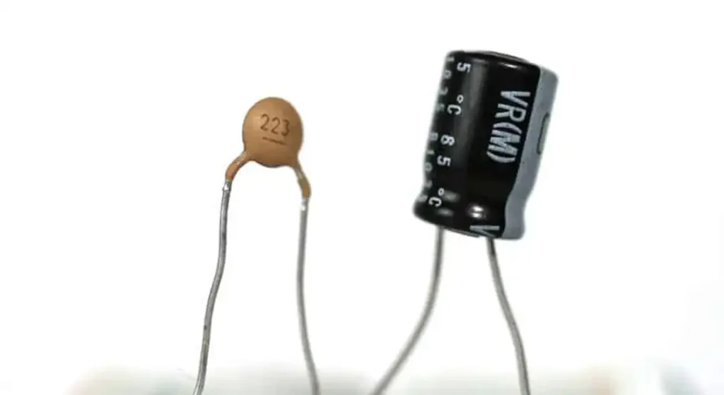
Identify the Capacitor Leads: Capacitors typically have two leads or terminals. In polarized capacitors, one lead is positive (+) and the other is negative (-), while in non-polarized capacitors, the leads are identical.
Determine Polarity (if applicable): If you’re using polarized capacitors such as electrolytic capacitors, it’s crucial to observe the polarity markings on the capacitor body. The longer lead or the lead with a “+” symbol usually denotes the positive terminal.
Prepare the Circuit: Ensure that the electronic circuit is powered off and disconnected from any power source to avoid electrical hazards or damage to components.
Choose the Mounting Orientation: Depending on the circuit layout and space constraints, determine whether the capacitor will be mounted vertically, horizontally, or in another orientation.
Insert the Leads: Insert the capacitor leads into the corresponding holes or solder pads on the circuit board. Make sure the leads are inserted fully and securely.
Solder the Leads (if applicable): If the circuit requires soldering, use a soldering iron to heat the joint where the capacitor lead meets the circuit board pad. Apply solder to form a strong electrical connection. Be careful not to overheat the capacitor, as excessive heat can damage it.
Trim Excess Leads (if applicable): If the capacitor leads extend beyond the solder joints, use wire cutters or flush cutters to trim them to an appropriate length, leaving a small amount of lead for stability.
Double-Check Connections: Verify that the capacitor is securely connected to the circuit board and that there are no solder bridges or cold joints that could cause electrical issues.
Insulate Exposed Leads (if necessary): If the capacitor leads are exposed and could come into contact with other components or conductive surfaces, insulate them using heat shrink tubing or electrical tape.
Test the Circuit: Once the capacitor is connected, power on the circuit and perform functional tests to ensure proper operation and stability. Monitor for any signs of overheating or abnormal behavior.
By following these steps, you can safely and effectively connect capacitors in electronic circuits, ensuring reliable performance and longevity. Always refer to the circuit schematic and manufacturer’s guidelines for specific instructions and precautions related to your capacitor and circuit configuration.
How to Connect a Capacitor in a Circuit?
Connecting a capacitor in a circuit requires careful consideration of the capacitor type, polarity (if applicable), and the intended function within the circuit.
Here’s a general guide on how to connect a capacitor in a circuit:
Identify Capacitor Leads: Capacitors typically have two leads or terminals. If the capacitor is polarized (such as an electrolytic capacitor), one lead will be marked positive (+) and the other negative (-). Non-polarized capacitors do not have polarity markings.
Determine Polarity (if applicable): If you’re using a polarized capacitor, ensure you identify the positive and negative terminals correctly. The longer lead or the lead with a “+” symbol usually denotes the positive terminal.
Prepare the Circuit: Before connecting the capacitor, ensure that the circuit is powered off and disconnected from any power source to prevent electrical hazards.
Choose Mounting Orientation: Depending on the circuit layout and space constraints, determine the best orientation for mounting the capacitor. It can be mounted vertically, horizontally, or at an angle as per the design requirements.
Connect Leads to Circuit: Insert the capacitor leads into the corresponding holes or solder pads on the circuit board. Ensure that the leads are inserted fully and securely.
Solder Leads (if necessary): If soldering is required, use a soldering iron to heat the joint where the capacitor lead meets the circuit board pad. Apply solder to form a strong electrical connection. Be cautious not to overheat the capacitor, as excessive heat can damage it.
Trim Excess Leads (if necessary): If the capacitor leads extend beyond the solder joints, trim them to an appropriate length using wire cutters or flush cutters, leaving a small amount of lead for stability.
Double-Check Connections: Verify that the capacitor is securely connected to the circuit board and that there are no solder bridges or cold joints that could cause electrical issues.
Insulate Exposed Leads (if necessary): If the capacitor leads are exposed and could come into contact with other components or conductive surfaces, insulate them using heat shrink tubing or electrical tape.
Test the Circuit: Once the capacitor is connected, power on the circuit and perform functional tests to ensure proper operation and stability. Monitor for any signs of overheating or abnormal behavior.
By following these steps, you can safely and effectively connect a capacitor in an electronic circuit, ensuring reliable performance and functionality. Always refer to the circuit schematic and manufacturer’s guidelines for specific instructions and precautions related to your capacitor and circuit configuration.
How to Connect A Capacitor to different Scenarios
Here’s a table showing how to connect capacitors in various scenarios:
| Scenario | Connection Method |
|---|---|
| How to a capacitor to AC | Connect one terminal of the capacitor to the live (hot) wire and the other terminal to the neutral wire. Ensure proper insulation and safety precautions. |
| How to a capacitor to a battery | Connect the positive terminal of the capacitor to the positive terminal of the battery and the negative terminal of the capacitor to the negative terminal of the battery. Ensure correct polarity. |
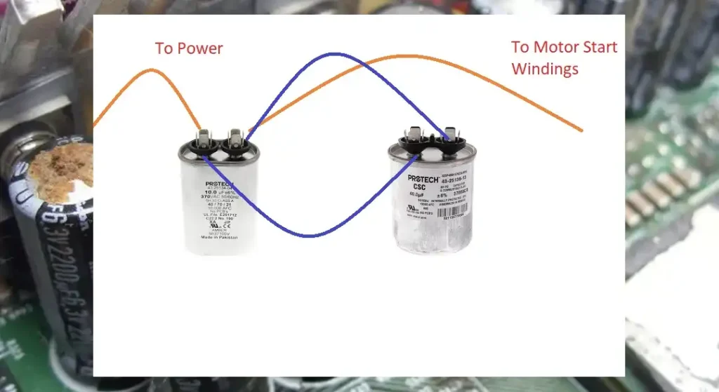
| How to a capacitor to a compressor | Connect the capacitor between the start and run terminals of the compressor motor. Refer to the compressor motor’s wiring diagram for proper connection. |
| How to a capacitor to a speaker | Connect the capacitor in series with the speaker to create a high-pass filter. Connect one terminal of the capacitor to the speaker’s positive terminal and the other terminal to the positive terminal of the amplifier. |
| How to a capacitor to an amp | Connect the capacitor in parallel with the power supply terminals of the amplifier. This helps stabilize voltage fluctuations and improve performance. |
| How to a capacitor to an amplifier | Similar to connecting to an amp, connect the capacitor in parallel with the power supply terminals of the amplifier. Ensure proper polarity and insulation. |
| How to a capacitor with 4 terminals | If the capacitor has four terminals, it may be a dual capacitor. Connect each terminal to the corresponding terminal in the circuit according to the manufacturer’s instructions or wiring diagram. |
| How to a dual capacitor | Connect each terminal of the dual capacitor to the corresponding terminal in the circuit according to the manufacturer’s instructions or wiring diagram. Dual capacitors typically serve multiple functions, such as starting and running motors in HVAC systems. |
| How to a run capacitor | Connect the run capacitor in series with the start winding of a single-phase motor to improve motor performance and efficiency. Refer to the motor’s wiring diagram for proper connection. |
| How to an electrolytic capacitor | Ensure correct polarity when connecting electrolytic capacitors. Connect the positive terminal to the higher voltage or positive side of the circuit and the negative terminal to the lower voltage or negative side of the circuit. |
These are general guidelines, and it’s essential to refer to the specific equipment’s wiring diagram or manufacturer’s instructions for precise connection methods and safety precautions.
Capacitors Connected in Parallel
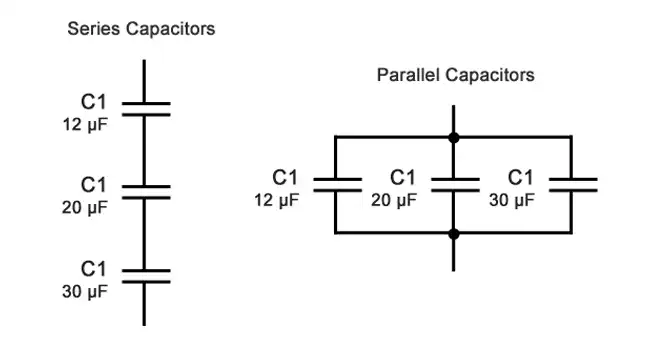
How to connect 2 capacitors in parallel?
When capacitors are connected in parallel in an electronic circuit, their positive terminals are connected together, and their negative terminals are also connected. This arrangement allows the capacitors to share the total charge applied across them while maintaining the same voltage across each capacitor.
Here’s how capacitors connected in parallel behave:
Total Capacitance: When capacitors are connected in parallel, the total capacitance (C_total) of the combination is the sum of the individual capacitances (C1, C2, C3, …, Cn) of each capacitor: C_total = C1 + C2 + C3 + … + Cn This means that the total capacitance increases as more capacitors are added in parallel.
Voltage Across Capacitors: In a parallel configuration, each capacitor has the same voltage (V) applied across it as the total voltage across the circuit. This is because the voltage across parallel components in a circuit is always the same.
Charge Distribution: When connected in parallel, capacitors share the total charge (Q) applied across them. The charge stored in each capacitor is proportional to its capacitance: Q1 = C1 * V
Q2 = C2 * V
Q3 = C3 * V
…
Qn = Cn * V
Equivalent Capacitance: The combination of capacitors in parallel can be replaced by a single capacitor with an equivalent capacitance (C_eq) equal to the sum of the individual capacitances: C_eq = C1 + C2 + C3 + … + Cn
Connecting capacitors in parallel is commonly used to increase the total capacitance in a circuit, providing greater energy storage capacity and improved filtering or smoothing of voltage fluctuations. It’s important to ensure that the voltage rating of each capacitor is sufficient for the total voltage applied across the parallel combination to avoid damage.
Capacitor Connected in Series
How to connect 2 capacitors in series?
When capacitors are connected in series in an electronic circuit, their positive terminals are connected to the negative terminals of adjacent capacitors, forming a chain-like configuration. In series connection, the voltage across each capacitor is different, but the total charge stored in the capacitors remains the same.
Here’s how capacitors connected in series behave:
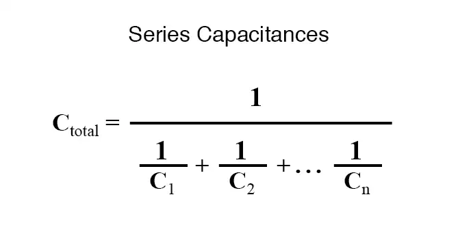
Total Capacitance: When capacitors are connected in series, the reciprocal of the total capacitance (C_total) of the combination is equal to the sum of the reciprocals of the individual capacitances (C1, C2, C3, …, Cn) of each capacitor: 1/C_total = 1/C1 + 1/C2 + 1/C3 + … + 1/Cn Unlike parallel connection, the total capacitance decreases as more capacitors are added in series.
Voltage Distribution: In a series configuration, each capacitor has a different voltage (V1, V2, V3, …, Vn) across it, determined by the total voltage (V_total) applied across the series combination and the individual capacitances: V_total = V1 + V2 + V3 + … + Vn
Charge Distribution: Despite having different voltages across them, the total charge (Q) stored in each capacitor is the same in a series connection. The charge stored in each capacitor is proportional to its capacitance: Q_total = Q1 = Q2 = Q3 = … = Qn
Equivalent Capacitance: The combination of capacitors in series can be replaced by a single capacitor with an equivalent capacitance (C_eq) calculated using the formula: 1/C_eq = 1/C1 + 1/C2 + 1/C3 + … + 1/Cn
Connecting capacitors in series is often used to achieve specific capacitance values or voltage ratings not readily available with individual capacitors. However, it’s essential to ensure that the voltage rating of each capacitor is sufficient for the voltage applied across it to prevent breakdown or damage. Additionally, series connection increases the risk of failure as the failure of one capacitor can affect the entire series chain.
Conclusion
In conclusion, connecting capacitors correctly is essential for maintaining the integrity and efficiency of electronic circuits. By understanding the various types, symptoms of failure, causes, diagnostic methods, and preventive measures, you can ensure smooth operation and longevity of your electronic devices.