Decoupling capacitors are fundamental components in electronics, yet beginners can often misunderstand their purpose and function. In this article, we will explore decoupling capacitors, their purpose, various types, and how to select and place them in circuits.
We’ll also cover the differences between decoupling and bypass capacitors and provide practical examples. By the end, you’ll clearly understand why these components are essential in electronic design.
What is a Decoupling Capacitor?

A decoupling capacitor, also known as a bypass capacitor, is used in electronic circuits to filter out unwanted noise and stabilize voltage levels. These capacitors are typically placed between the power supply and ground to smooth out voltage fluctuations. They serve as local energy reservoirs, providing instantaneous current to ICs (integrated circuits) and preventing voltage drops caused by sudden current demands.
Decoupling Capacitor Purpose

The primary purpose of a decoupling capacitor is to filter out high-frequency noise from power lines. These noises can originate from various sources such as switching power supplies, digital circuits, and electromagnetic interference (EMI). Placing a decoupling capacitor close to an IC ensures that the IC receives a stable voltage, free from high-frequency fluctuations that can cause malfunction or erratic behavior.
How Decoupling Capacitors Work

Decoupling capacitors play a crucial role in keeping electronic circuits running smoothly, but how exactly do they do it?
Well, think of them as the guardians of a clean power supply. When electronic devices are at work, they generate all sorts of high-frequency noise that can interfere with their proper functioning. This noise can come from various sources like switching transistors or even just the operation of the circuits themselves.
Now, imagine this noise as little troublemakers running wild in your system, causing disturbances and fluctuations in the power supply. That’s where the decoupling capacitor steps in like a superhero. It acts as a sort of traffic cop, directing all that pesky noise away from the sensitive parts of the circuit and toward the ground.
So, when the noise comes knocking, the decoupling capacitor provides a shortcut straight to the ground, offering it a cozy low-impedance path to follow. This effectively diverts the noise away from the power supply lines that feed the integrated circuits (ICs).
With the noise out of the way, the power supply lines can now deliver a steady, uninterrupted flow of DC voltage to the ICs, ensuring they operate smoothly and without any glitches.
In essence, decoupling capacitors act as silent protectors, quietly ensuring that the power supply remains stable and free from the disruptive influence of high-frequency noise. They may be small components, but their role in maintaining the reliability and performance of electronic systems is absolutely essential.
Decoupling Capacitor Value
Choosing the correct value for a decoupling capacitor is crucial. Common values range from 100nF (0.1µF) to several microfarads (µF). For example, a 100nF decoupling capacitor is typical for high-frequency noise filtering, while a 1µF decoupling capacitor might be used for lower-frequency noise.
Calculating Decoupling Capacitor Values
When selecting the appropriate value for decoupling capacitors, it’s essential to consider the frequency range of the noise that needs to be filtered. Ceramic capacitors are commonly used for high-frequency applications due to their low Equivalent Series Resistance (ESR) and Equivalent Series Inductance (ESL), making them effective in filtering out high-frequency noise.
To calculate the value of a decoupling capacitor, you can use the following guidelines:
- Identify the Frequency Range: Determine the frequency range of the noise that needs to be filtered. This could include noise from switching power supplies, digital circuits, or electromagnetic interference.
- Choose Capacitor Type: Select the type of capacitor based on the frequency range. For high-frequency noise, ceramic capacitors are preferred due to their low ESR and ESL.
- Use Decoupling Capacitor Calculators: Online calculators are available to help determine the appropriate capacitance value based on the frequency range of the noise. These calculators take into account factors such as the load current, frequency, and acceptable voltage ripple.
Decoupling Capacitor Placement
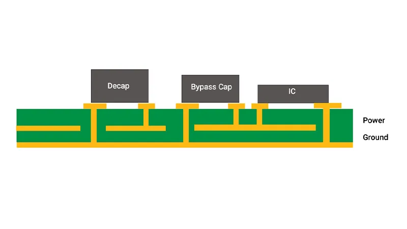
Proper placement of decoupling capacitors is critical for their effectiveness. They should be placed as close as possible to the power pins of the IC they are protecting. This minimizes the loop area and inductance, enhancing the capacitor’s ability to filter noise effectively.
Types of Decoupling Capacitors

Decoupling capacitors come in various types, each suited for different applications:
Ceramic Capacitors: These are go-to components for high-frequency applications, thanks to their low ESR (Equivalent Series Resistance) and ESL (Equivalent Series Inductance). Ceramic capacitors provide excellent performance in terms of high-frequency filtering and decoupling. They come in different types, such as multi-layer ceramic capacitors (MLCCs), offering various capacitance values and voltage ratings to suit different requirements.
Tantalum Capacitors: Ideal for applications with lower frequencies, tantalum capacitors offer stable capacitance over a wide temperature range. They are known for their reliability and longevity, making them suitable for critical applications where performance consistency is essential. Tantalum capacitors come in both solid and electrolytic forms, with solid tantalum capacitors being more commonly used in decoupling applications due to their lower ESR and higher reliability.
Electrolytic Capacitors: These capacitors excel in bulk decoupling tasks, where filtering out low-frequency noise and providing large capacitance values are crucial. They offer cost-effective solutions for applications requiring significant energy storage and filtering capabilities. Electrolytic capacitors are available in both aluminum and tantalum variations, with aluminum electrolytic capacitors being more commonly used for general-purpose decoupling due to their higher capacitance values and lower cost.
| Capacitor Type | Advantages |
| Ceramic Capacitors | – Low ESR and ESL, ideal for high-frequency applications |
| – Wide range of capacitance values and voltage ratings for flexibility in design | |
| Tantalum Capacitors | – Stable capacitance over a wide temperature range |
| – Reliability and longevity, suitable for critical applications | |
| Electrolytic Capacitors | – High capacitance values for bulk decoupling tasks |
| – Cost-effective solution for applications requiring significant energy storage and filtering |
Application of Decoupling Capacitors
Decoupling Capacitor in VLSI
In Very Large Scale Integration (VLSI) circuits, on-chip decoupling capacitors are used to stabilize power supply lines. These capacitors are integrated into the chip design to provide immediate current to the transistors, improving performance and reducing noise.
Decoupling Capacitors in Audio Applications
Audio decoupling capacitors are used to remove noise from power supplies in audio circuits. High-quality capacitors are essential to maintain audio fidelity and prevent unwanted noise from affecting audio signals.
Decoupling Capacitors in Arduino Projects
In Arduino projects, decoupling capacitors are used to stabilize the power supply to the microcontroller and other components. Typical values range from 100nF to 1µF, placed close to the power pins of the microcontroller.
High-Frequency Decoupling Capacitors
For high-frequency applications, ceramic capacitors are preferred due to their low ESR and ESL, providing effective noise filtering at high frequencies.
Bulk Decoupling Capacitors
Bulk capacitors are used in power supply decoupling to handle large, low-frequency noise. They complement smaller decoupling capacitors to ensure a stable power supply across all frequency ranges.
How to Choose a Decoupling Capacitor
Choosing the right decoupling capacitor involves considering several factors:
- Frequency Range: Determine the frequency range of the noise you need to filter.
- Capacitance Value: Use decoupling capacitor calculators to select appropriate values.
- Type of Capacitor: Choose based on the application, whether it’s high-frequency, audio, or bulk decoupling.
- Placement: Ensure proper placement to maximize effectiveness.
Decoupling Capacitor Layout in PCBs

In PCB (Printed Circuit Board) design, the layout of decoupling capacitors is crucial. Guidelines include:
- Close Placement: Position capacitors close to IC power pins.
- Minimize Inductance: Use short, wide traces to reduce inductance.
- Ground Plane: Connect capacitors to a solid ground plane for effective noise filtering.
Decoupling Capacitor Schematic Design
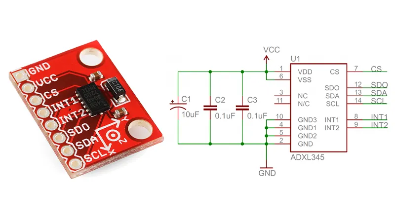
In the schematic design, decoupling capacitors are shown connected between the power supply line and ground, placed near the power pins of each IC. This ensures each IC receives filtered, stable power.
Bypass Capacitor vs Decoupling Capacitor
The terms “bypass capacitor” and “decoupling capacitor” are often used interchangeably, but they can have slightly different connotations depending on the context. Both serve similar functions in filtering noise and stabilizing voltage, but “bypass” often emphasizes the capacitor’s role in providing a path for high-frequency noise, while “decoupling” emphasizes isolating different parts of the circuit to prevent interference.
Conclusion
Decoupling capacitors play a vital role in electronic circuits, ensuring stable voltage supply and filtering out unwanted noise. Understanding their purpose, how they work, and how to select and place them correctly can significantly improve the performance and reliability of your electronic designs.
Whether you’re working with Arduino projects, audio applications, or complex VLSI circuits, proper use of decoupling capacitors is essential. By following the guidelines and principles outlined in this article, you can effectively implement decoupling capacitors in your circuits and achieve optimal performance.