Understanding crystal oscillator waveforms is crucial for ensuring proper integration within electronic systems. These devices provide stable frequency signals, but the output type significantly impacts performance. This guide explores the various waveforms generated by crystal oscillators, detailing their characteristics and applications.
From CMOS to LVPECL, each waveform possesses unique attributes that determine its suitability for specific circuits. We’ll delve into the nuances of these output types, providing insights into their advantages and limitations. This knowledge empowers engineers to select the optimal crystal oscillator for their design needs.
What Are Crystal Oscillators
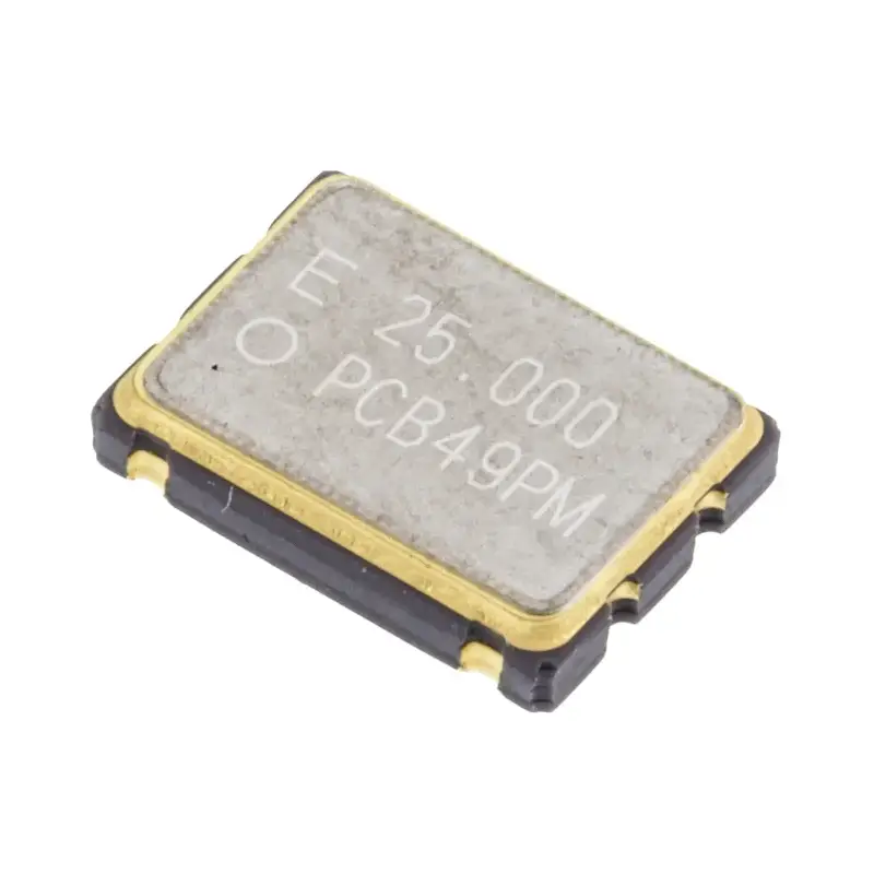
Crystal oscillators are electronic circuits that generate a precise and stable frequency signal by utilizing the piezoelectric properties of quartz crystals. When a voltage is applied to a quartz crystal, it vibrates at a specific resonant frequency, determined by its physical dimensions and cut. This vibration, in turn, produces an electrical signal. This highly stable frequency output makes crystal oscillators essential components in various electronic devices that require accurate timing.
These oscillators are fundamental in applications ranging from microprocessors and communication systems to consumer electronics and industrial equipment. They serve as the heartbeat of digital systems, providing the clock signal that synchronizes operations. Their accuracy and reliability make them indispensable for tasks requiring precise timing, such as data transmission, signal processing, and timekeeping. The stability of the crystal ensures that the generated frequency remains consistent, even under varying temperature and environmental conditions.
What Is Crystal Oscillator Waveform
A crystal oscillator waveform refers to the shape of the electrical signal produced by a crystal oscillator circuit. This waveform is critical because it dictates how the oscillator’s output interacts with other components in an electronic system.
The most common waveforms are square waves, sine waves, and clipped sine waves, each with distinct characteristics. Square waves are widely used in digital systems due to their sharp transitions, while sine waves are preferred in analog and RF applications for their purity. The choice of waveform depends on the specific requirements of the application, such as frequency stability, signal integrity, and power consumption.
Crystal Oscillator Waveform Types
Crystal oscillators are the heart of many electronic systems, providing the stable timing signals that synchronize operations. However, the output of these oscillators isn’t uniform; it comes in various waveform types, each tailored for specific applications.
Understanding these waveforms is crucial for engineers and designers, as selecting the right type ensures optimal performance and compatibility within a circuit. From the sharp transitions of CMOS and LVCMOS to the high-speed differential signals of LVPECL and the smooth purity of sine waves, each waveform offers unique characteristics that cater to diverse electronic needs.
CMOS (Complementary Metal-Oxide-Semiconductor)
CMOS output waveforms are characterized by their rail-to-rail swing, meaning the signal transitions between the power supply voltage (Vdd) and ground (GND). This results in a sharp, square-like waveform with fast rise and fall times, making it ideal for digital applications. CMOS oscillators are known for their low power consumption, which is a significant advantage in battery-powered or energy-sensitive devices. The high impedance output of CMOS allows for easy interfacing with other CMOS logic devices.
The output signal of a CMOS oscillator has well-defined logic levels, ensuring reliable digital signal transmission. The sharp transitions of the waveform minimize signal distortion and enable precise timing in digital circuits. CMOS oscillators are widely used in microcontrollers, memory devices, and other digital systems where accurate and low-power clock signals are essential. Their robustness and compatibility with various digital ICs make them a popular choice for a wide range of applications.
However, the fast rise and fall times of CMOS signals can generate electromagnetic interference (EMI) if not properly managed. Proper layout techniques and filtering are often necessary to mitigate EMI issues. Additionally, the output drive strength of CMOS oscillators may be limited, requiring buffering for driving heavy loads or long transmission lines. Despite these considerations, CMOS oscillators remain a staple in digital electronics due to their efficiency and versatility.
TTL (Transistor-Transistor Logic)
TTL output waveforms are defined by their specific voltage levels, typically around 5V, and are characterized by a square-like shape with relatively fast rise and fall times. TTL oscillators are designed to interface with TTL logic devices, which were prevalent in older digital systems. They are known for their robust drive capability, enabling them to drive multiple TTL loads without significant signal degradation.
The output signal of a TTL oscillator has well-defined voltage thresholds, ensuring reliable logic level detection. The output impedance is relatively low, allowing for good signal integrity and noise immunity. TTL oscillators are commonly used in applications where backward compatibility with older TTL logic is required, or in situations where robust drive capability is essential. They are often found in industrial control systems, test equipment, and legacy digital devices.
However, TTL oscillators consume more power compared to CMOS oscillators, which can be a disadvantage in power-sensitive applications. Additionally, the voltage levels of TTL signals may not be compatible with newer low-voltage logic devices, requiring level shifting or other interface circuitry. Despite these limitations, TTL oscillators remain relevant in specific applications where their robust drive capability and backward compatibility are crucial.
LVCMOS (Low-Voltage Complementary Metal-Oxide-Semiconductor)
LVCMOS output waveforms are similar to CMOS, but they operate at lower voltage levels, typically 3.3V, 2.5V, or 1.8V. This makes them suitable for modern low-power digital systems. LVCMOS oscillators provide a rail-to-rail swing between the supply voltage and ground, resulting in sharp, square-like waveforms with fast rise and fall times. They are known for their low power consumption and compatibility with a wide range of low-voltage logic devices.
The output signal of an LVCMOS oscillator has well-defined logic levels, ensuring reliable digital signal transmission in low-voltage environments. The sharp transitions of the waveform minimize signal distortion and enable precise timing in digital circuits. LVCMOS oscillators are widely used in portable devices, microcontrollers, and other low-power digital systems where energy efficiency is critical. Their compatibility with various low-voltage ICs makes them a popular choice for modern electronic designs.
Like CMOS, LVCMOS signals can generate EMI due to their fast rise and fall times. Proper layout techniques and filtering are necessary to mitigate EMI issues. The output drive strength of LVCMOS oscillators may also be limited, requiring buffering for driving heavy loads or long transmission lines. Despite these considerations, LVCMOS oscillators are essential for modern low-power electronics due to their efficiency and compatibility.
LVPECL (Low-Voltage Positive Emitter-Coupled Logic)
LVPECL output waveforms are characterized by their differential signaling and low voltage levels, typically around 3.3V or 2.5V. Unlike single-ended signals, LVPECL signals use two complementary outputs, providing improved noise immunity and signal integrity. LVPECL oscillators are designed for high-speed applications, such as telecommunications, data communications, and high-frequency clock distribution. They are known for their high drive capability and ability to transmit signals over long distances with minimal signal degradation.
The differential signaling of LVPECL reduces common-mode noise and crosstalk, making it suitable for noisy environments. The low voltage swing of LVPECL signals minimizes power consumption at high frequencies. LVPECL oscillators are commonly used in applications requiring high-speed data transmission, such as Ethernet, Fibre Channel, and PCI Express. They are also used in RF systems and other high-frequency applications where signal integrity is critical.
However, LVPECL oscillators require differential receivers and careful impedance matching to ensure proper signal termination and minimize reflections. They also consume more power compared to CMOS or LVCMOS oscillators, which can be a disadvantage in power-sensitive applications. Despite these considerations, LVPECL oscillators are essential for high-speed applications where signal integrity and performance are paramount.
Sine Wave
Sine wave output waveforms are characterized by their smooth, continuous oscillations, resembling a pure sinusoidal signal. Sine wave oscillators are used in analog and RF applications where signal purity and low harmonic distortion are essential. They are known for their excellent frequency stability and low phase noise. Sine wave oscillators are commonly used in communication systems, signal generators, and other applications requiring high-fidelity signals.
The smooth waveform of a sine wave oscillator minimizes harmonic distortion and spurious signals, making it suitable for sensitive analog circuits. The frequency stability of sine wave oscillators is typically very high, ensuring accurate and reliable signal generation. They are often used in applications where precise frequency control is required, such as frequency synthesizers and RF transmitters.
However, sine wave oscillators may require external filtering or amplification to achieve the desired signal level and purity. They also consume more power compared to digital oscillators, which can be a disadvantage in power-sensitive applications. Despite these considerations, sine wave oscillators are essential for analog and RF applications where signal purity and frequency stability are critical.
Table of Crystal Oscillator Waveform Types:
| Waveform Type | Voltage Levels | Characteristics | Applications | Advantages | Disadvantages |
| CMOS | Vdd to GND | Square wave, fast rise/fall times | Microcontrollers, digital circuits | Low power, compatibility | EMI, limited drive strength |
| TTL | ~5V | Square wave, robust drive | Legacy digital systems, industrial control | Robust drive, backward compatibility | High power, limited compatibility |
| LVCMOS | 3.3V, 2.5V, 1.8V | Square wave, low voltage | Portable devices, low-power systems | Low power, low voltage | EMI, limited drive strength |
| LVPECL | Differential, ~3.3V, 2.5V | Differential signaling, high speed | Telecommunications, data communications | High speed, noise immunity | High power, complex termination |
| Sine Wave | Analog, continuous | Smooth, sinusoidal waveform | Analog circuits, RF systems | Signal purity, frequency stability | High power, filtering required |
How Do You Find the Output Waveform?
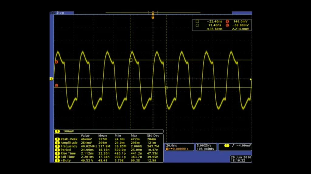
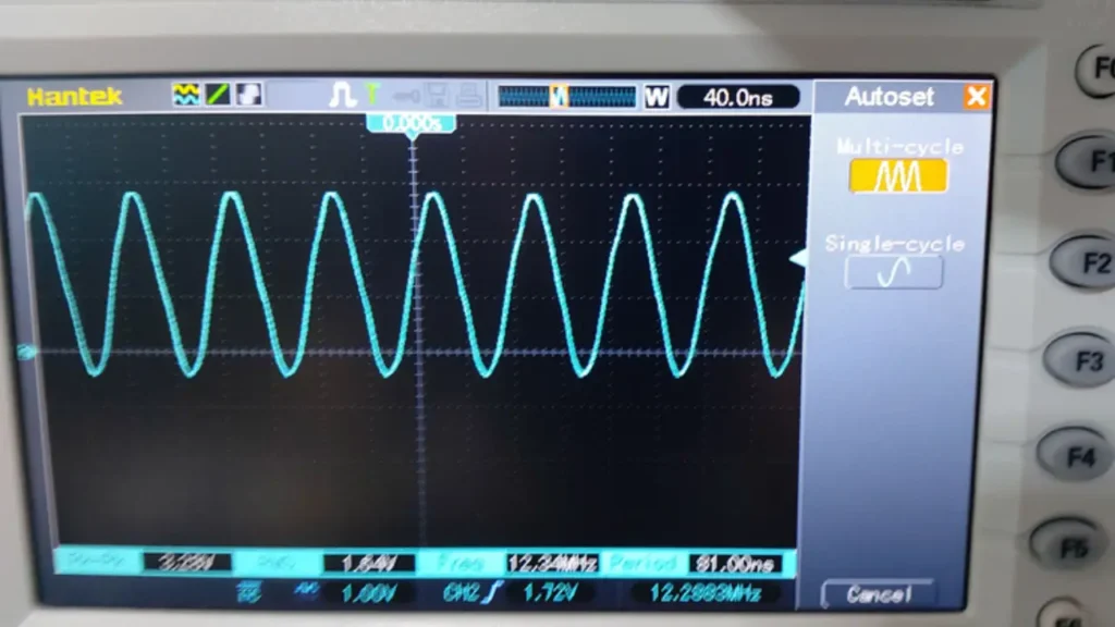
Finding the output waveform of a crystal oscillator involves a combination of measurement techniques and datasheet analysis. The most common method is using an oscilloscope. An oscilloscope allows you to visualize the electrical signal in real-time, displaying its voltage levels and shape over time. By connecting the oscilloscope probes to the oscillator’s output pins, you can observe the waveform’s characteristics, such as its rise and fall times, voltage swing, and overall shape. This direct measurement provides a clear picture of the signal’s behavior under actual operating conditions.
Another crucial step is consulting the oscillator’s datasheet. Manufacturers provide detailed specifications, including typical output waveforms and their associated characteristics. The datasheet will specify the expected voltage levels, rise and fall times, and any other relevant parameters for the chosen output type (CMOS, LVCMOS, LVPECL, sine wave, etc.). Comparing the measured waveform from the oscilloscope with the datasheet specifications allows you to verify the oscillator’s performance and ensure it meets the required standards.
In addition to direct measurement and datasheet analysis, simulation tools can be used during the design phase. Circuit simulation software can model the oscillator’s behavior, providing a predicted output waveform based on the circuit’s design and component values. This can be helpful for identifying potential issues and optimizing the circuit before physical prototyping. However, it’s always essential to validate simulation results with actual measurements using an oscilloscope to ensure accurate and reliable performance.
Conclusion
Understanding crystal oscillator waveforms is crucial for selecting the right oscillator for your application. Each output type, from CMOS to LVPECL, offers distinct characteristics impacting signal integrity and system performance. This guide has provided insights into the various oscillator output types, empowering you to make informed decisions for your electronic designs.
Choosing the correct waveform ensures optimal compatibility and reliability in your circuits. Whether you need precise timing for digital systems or high-frequency signals for communication devices, a thorough understanding of oscillator output types is essential. This knowledge directly translates to enhanced performance and efficiency in your projects.
For a comprehensive selection of high-quality crystal oscillators, including customizable options, explore Weishi Electronics. We offer wholesale solutions tailored to your specific needs, ensuring reliable performance and exceptional quality. Contact Weishi Electronics today to discuss your crystal oscillator requirements.