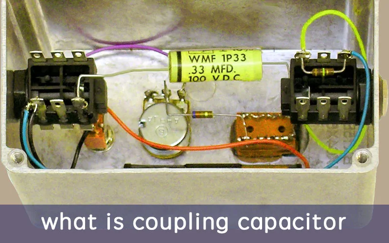
Application diagram of what is a coupling capacitor
What is a Coupling Capacitor?
A coupling capacitor, also referred to as capacitive coupling or electric field coupling, is a component within electrical systems that facilitates the transfer of energy between different circuits or components.
It operates through the principle of displacement current induced by the electric field, allowing for intentional or accidental energy transfer within an electrical network or between distant networks. An illustrative example is the coupling of vibrations between two pendulums connected by a wire, wherein the vibrations become coupled.
This phenomenon is akin to the distributed capacitance effect, where interactions between systems or forms of motion lead to coupled behavior. Coupling capacitors play a crucial role in various electronic applications, such as signal transmission, filtering, and impedance matching, by enabling the efficient transfer of energy while minimizing interference or distortion.
Schematic diagram of what is a coupling capacitor
How Coupling Capacitors Work?
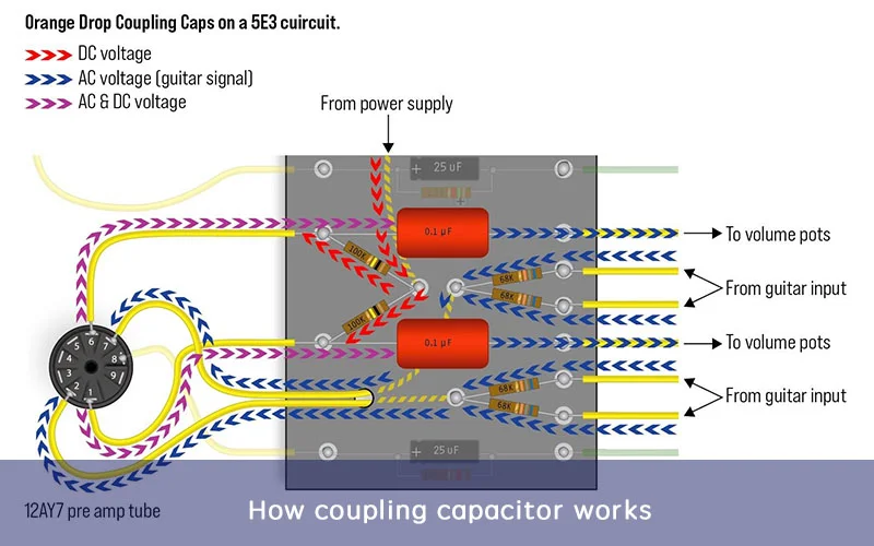
The coupling capacitor serves a crucial role in electronic circuits by separating strong and weak current systems, ensuring the safe transmission of high-frequency signals while blocking low-frequency interference.
In an AC circuit, the coupling capacitor gradually accumulates charge on one plate as the voltage increases during the positive half cycle of the AC waveform. When the voltage decreases in the negative half cycle, the accumulated charge is released back into the circuit. This cyclical process creates the illusion of current flow through the capacitor, even though no actual current traverses its entirety.
The capacitor’s ability to block DC while allowing AC to pass is due to its capacity to store and release charge without forming a complete circuit loop. DC voltage can charge the capacitor, but once the voltage stabilizes, no current flows, effectively isolating the DC component.
By continuously charging and discharging during each cycle of the AC signal, the capacitor provides a pathway for AC current to pass through, facilitating signal transmission to subsequent circuit components. This mechanism ensures that the operating point of the following stage amplifier circuit remains unaffected by any DC bias present in the preceding stage.
Overall, the coupling capacitor’s operation relies on its ability to store and release charge in response to the fluctuating voltage of an AC signal, effectively separating AC and DC components for optimal circuit performance.
Functions of a Coupling Capacitor
The coupling capacitor serves a crucial role in electronic circuits by separating strong and weak current systems, ensuring the safe transmission of high-frequency signals while blocking low-frequency interference.
In an AC circuit, the coupling capacitor gradually accumulates charge on one plate as the voltage increases during the positive half cycle of the AC waveform. When the voltage decreases in the negative half cycle, the accumulated charge is released back into the circuit. This cyclical process creates the illusion of current flow through the capacitor, even though no actual current traverses its entirety.
The capacitor’s ability to block DC while allowing AC to pass is due to its capacity to store and release charge without forming a complete circuit loop. DC voltage can charge the capacitor, but once the voltage stabilizes, no current flows, effectively isolating the DC component.
By continuously charging and discharging during each cycle of the AC signal, the capacitor provides a pathway for AC current to pass through, facilitating signal transmission to subsequent circuit components. This mechanism ensures that the operating point of the following stage amplifier circuit remains unaffected by any DC bias present in the preceding stage.
Overall, the coupling capacitor’s operation relies on its ability to store and release charge in response to the fluctuating voltage of an AC signal, effectively separating AC and DC components for optimal circuit performance.
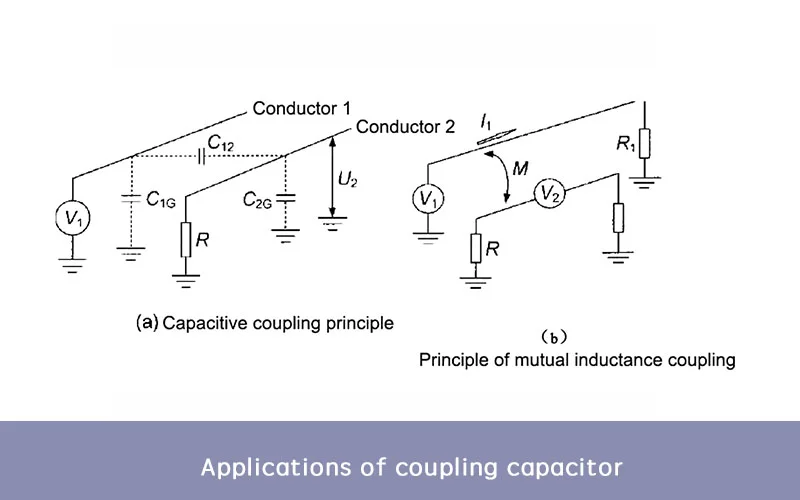
Coupling Modes of the Coupling Capacitor
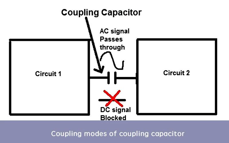
When it comes to interference in electronic control systems, various coupling methods facilitate its intrusion. Interference sources can affect systems through wires, spaces, or shared lines. Capacitor coupling encompasses several types:
Direct Coupling: This straightforward method involves interference signals directly infiltrating the system via wires, representing a common intrusion route. Filtering and decoupling techniques are effective in mitigating such interference.
Common Impedance Coupling: This method occurs when two circuits share a common path for current flow. Public ground and power supply impedance are two variants. Minimizing coupling impedance to near-zero levels prevents interference by eliminating common impedance between the source and the affected object.
Capacitive Coupling: Also known as electric field or electrostatic coupling, this method is prevalent in inverters like 2000-watt or 3000-watt solar inverters. Capacitors play a key role in signal transfer, converting DC to AC by modulating voltage through transformers or converters. Capacitive coupling finds application in inverter output and control circuits.
Electromagnetic Induction Coupling: Also called magnetic field coupling, this method relies on electromagnetic field induction within internal or external spaces. Shielding susceptible devices or circuits helps prevent this type of interference.
Radiation Coupling: Electromagnetic field radiation can induce interference coupling, often transmitted through power lines. Additionally, long signal transmission lines may act as antennas, radiating and receiving interference waves.
Leakage Coupling: Also known as resistive coupling, this interference occurs when insulation deteriorates. It can lead to irregular interference patterns.
Understanding these coupling modes aids in implementing effective interference mitigation strategies, ensuring the reliable operation of electronic control systems.
Parameters of Coupling Capacitor
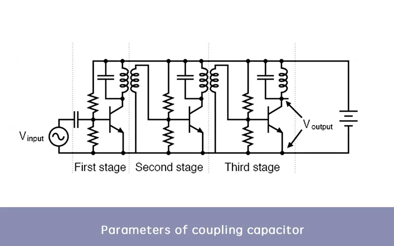
Choosing the appropriate coupling capacitor is critical to the performance of the circuit.
Here are a few parameters to consider when selecting coupling capacitors:
Capacitance (C): This parameter represents the amount of charge a capacitor can store per unit voltage. It is measured in farads (F) or submultiples like microfarads (μF) or picofarads (pF). Capacitance determines the ability of the capacitor to block or pass certain frequencies of signals.
Voltage Rating: The voltage rating indicates the maximum voltage that can be applied across the capacitor without risking damage or breakdown. It’s crucial to choose a capacitor with a voltage rating higher than the maximum voltage expected in the circuit.
Tolerance: Tolerance specifies the maximum allowable deviation from the nominal capacitance value. It’s expressed as a percentage and indicates the precision of the capacitor’s capacitance value. Common tolerance values include ±5%, ±10%, and ±20%.
Temperature Coefficient: This parameter describes how the capacitance of the capacitor changes with temperature variations. It’s specified in parts per million per degree Celsius (ppm/°C) or as a percentage change per degree Celsius.
Equivalent Series Resistance (ESR): ESR represents the internal resistance of the capacitor. It influences the capacitor’s ability to filter out noise and stabilize voltage in the circuit. Lower ESR values are desirable for better performance.
Leakage Current: Leakage current refers to the small amount of current that flows through the dielectric material of the capacitor, even when it’s fully charged. It’s essential to minimize leakage current, especially in applications where high insulation resistance is required.
Dielectric Material: The dielectric material used in the capacitor determines its properties such as dielectric constant, breakdown voltage, and temperature stability. Common dielectric materials include ceramic, aluminum electrolytic, tantalum, and polyester.
Understanding these parameters helps in selecting the right coupling capacitor for a particular circuit, ensuring optimal performance and reliability.
The Role of Coupling Capacitors in Signal Transmission
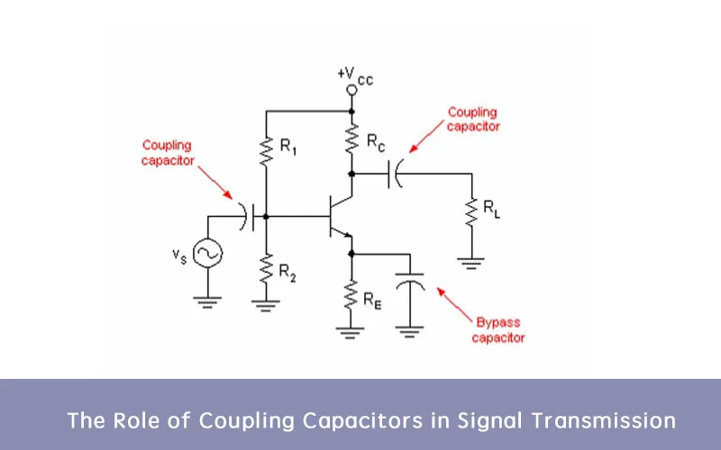
Coupling capacitors play a crucial role in signal transmission within electronic circuits, particularly in scenarios where it’s necessary to separate the AC and DC components of a signal. Here are the main roles of coupling capacitors:
Blocking DC Components: One primary function of coupling capacitors is to block DC voltage while allowing AC signals to pass through. This is essential in applications where DC biasing is present in one stage of the circuit but needs to be isolated from subsequent stages. By blocking DC, coupling capacitors prevent DC offsets from affecting the operation of downstream components.
Passing AC Signals: Coupling capacitors allow AC signals to pass through by charging and discharging in response to changes in the AC waveform. During the positive half-cycle of the AC signal, the capacitor charges up, and during the negative half-cycle, it discharges. This creates a pathway for the AC component of the signal to flow through the capacitor while blocking the DC component.
Maintaining Signal Integrity: By isolating AC and DC components, coupling capacitors help maintain the integrity of the signal as it travels through different stages of amplification or processing within a circuit. This prevents distortion or interference caused by DC offsets and ensures that the desired signal is accurately transmitted.
Preventing Saturation of Amplifiers: In amplifier circuits, coupling capacitors prevent the saturation of amplifiers by blocking any DC offset present in the input signal. This ensures that the amplifier operates within its linear range, avoiding distortion and improving overall signal fidelity.
Enabling Biased Coupling: Coupling capacitors also facilitate biased coupling, where both DC bias and AC signals are allowed to pass through while maintaining a specified bias voltage. This is useful in applications where both DC and AC components are required, such as in audio amplifiers with a predetermined operating point.
In summary, coupling capacitors serve to isolate AC and DC components of a signal, pass AC signals while blocking DC voltage, maintain signal integrity, prevent amplifier saturation, and enable biased coupling in electronic circuits. Their proper selection and placement are essential for ensuring optimal signal transmission and circuit performance.
Applications of Coupling Capacitor
Coupling capacitors find widespread use in various electronic circuits and systems due to their ability to transmit AC signals while blocking DC signals. Their versatile nature and effectiveness make them essential components in numerous applications. Here are some common applications of coupling capacitors:
Audio Amplifiers: In audio amplifiers, coupling capacitors are used to block DC voltage while allowing audio signals to pass through. This prevents DC bias from affecting the amplifier’s operation while ensuring that only the audio signal is amplified, leading to improved sound quality.
Radio Frequency (RF) Circuits: Coupling capacitors are employed in RF circuits to couple RF signals between stages while blocking DC bias. This allows for the transmission and amplification of RF signals without distortion, enabling efficient communication in wireless systems and radio receivers.
Power Supplies: In power supply circuits, coupling capacitors are used to filter out AC ripple voltage from DC power sources. By connecting capacitors across the output terminals of rectifiers, coupling capacitors smooth out fluctuations in voltage, ensuring stable and reliable power delivery to electronic devices.
Signal Processing Circuits: Coupling capacitors play a crucial role in signal processing circuits, such as filters and equalizers, where they help to separate AC signals from DC components. This allows for precise manipulation of signal frequency, amplitude, and phase, leading to enhanced signal processing capabilities.
DC Blocking Circuits: Coupling capacitors are commonly used in circuits where DC blocking is necessary to prevent damage to sensitive components or to isolate different stages of a circuit. By blocking DC voltage, coupling capacitors help maintain signal integrity and prevent unwanted interactions between circuit elements.
Sensor Interfaces: In sensor interfaces and measurement circuits, coupling capacitors are utilized to remove DC offset and bias from sensor outputs, allowing for accurate signal measurement and analysis. This ensures that sensor readings are not affected by baseline shifts or environmental factors.
Audio and Video Coupling: Coupling capacitors are employed in audio and video circuits to couple audio and video signals between different components, such as amplifiers, speakers, and displays. This ensures seamless signal transmission and enhances the overall performance of audio and video systems.
Impedance Matching Networks: Coupling capacitors are integrated into impedance matching networks to optimize signal transfer between different impedance levels. By adjusting the coupling capacitance, impedance-matching networks ensure maximum power transfer and minimize signal reflections in transmission lines and antennas.
Types of Coupling capacitors
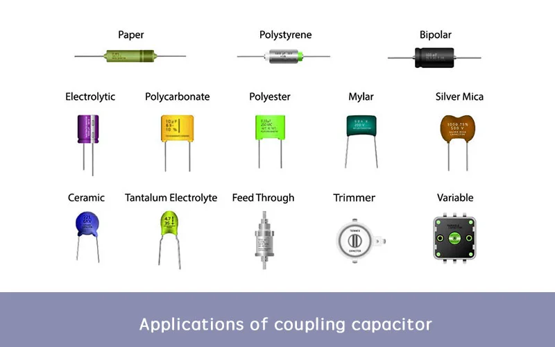
Certainly! Coupling capacitors are used to pass AC signals while blocking DC components in electronic circuits. Here are some common types:
Electrolytic Capacitors: These are polarized capacitors commonly used in coupling applications due to their relatively high capacitance values and low cost. However, they are typically not suitable for high-frequency signals due to their relatively high equivalent series resistance (ESR) and inductance.
Film Capacitors: Film capacitors, such as polyester (Mylar), polypropylene, and polycarbonate, are non-polarized capacitors that offer good performance across a wide range of frequencies. They are often preferred for coupling applications where low distortion and high stability are important.
Ceramic Capacitors: While ceramic capacitors are more commonly used for decoupling, they can also be used as coupling capacitors in certain applications, especially at lower frequencies. They offer low ESR and are available in a wide range of capacitance values.
Tantalum Capacitors: Tantalum capacitors can also be used as coupling capacitors, particularly in applications where space is limited and relatively high capacitance values are required. However, they are polarized and typically have higher ESR compared to film capacitors.
Mica Capacitors: Mica capacitors are known for their high stability and low losses, making them suitable for high-frequency coupling applications where precision and low distortion are critical. However, they are less common and more expensive compared to other types.
When selecting a coupling capacitor, factors such as capacitance value, voltage rating, frequency response, distortion, and size should be considered based on the specific requirements of the circuit and application.
How to Select the Right Coupling Capacitors?
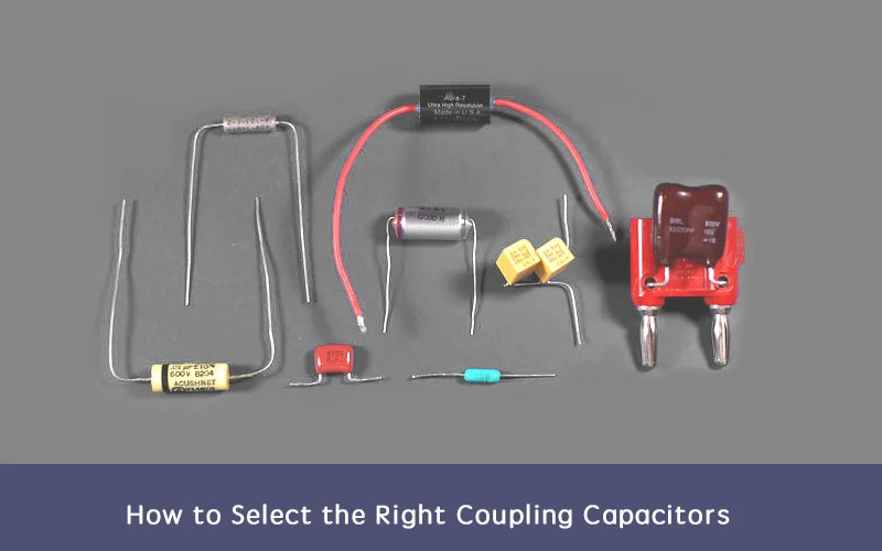
Selecting the right coupling capacitor involves considering several factors to ensure optimal performance in your circuit:
Capacitance Value: Determine the required capacitance based on the frequency range of the signals you want to couple. Lower frequencies typically require larger capacitance values, while higher frequencies may need smaller capacitance values.
Voltage Rating: Choose a capacitor with a voltage rating higher than the maximum voltage present in your circuit to prevent breakdown or damage. It’s good practice to select a capacitor with a voltage rating at least 1.5 times greater than the maximum voltage in your circuit.
Frequency Response: Consider the frequency response of the capacitor, especially if you’re dealing with AC signals across a wide range of frequencies. Capacitors with low ESR and ESL (Equivalent Series Inductance) are preferable for high-frequency applications to minimize distortion.
Dielectric Material: Different dielectric materials (e.g., ceramic, film, electrolytic) have varying characteristics such as stability, temperature coefficient, and losses. Choose the dielectric material that best suits your application requirements, considering factors like frequency stability, tolerance, and temperature range.
Tolerance: Capacitors have a specified tolerance indicating how much their actual capacitance may deviate from the labeled value. Select capacitors with tolerances appropriate for your circuit’s sensitivity to capacitance variations.
Size and Package: Consider the physical size and package type of the capacitor, especially if space is limited on your PCB. Surface-mount capacitors are often preferred for compact designs, while through-hole capacitors may be more suitable for larger, less space-constrained circuits.
Cost: Balance performance requirements with cost constraints. While high-performance capacitors may offer superior characteristics, they may also come with a higher price tag. Evaluate your budget and prioritize features accordingly.
Application-Specific Considerations: Take into account any unique requirements of your circuit or application, such as temperature extremes, environmental conditions, or special performance criteria.
By carefully considering these factors and selecting coupling capacitors that align with your circuit’s requirements, you can ensure reliable signal coupling and optimal performance in your electronic designs.
Conclusion
Coupling capacitors are indispensable components in electronic circuits, facilitating the efficient transmission of AC signals while blocking DC components.
Their versatile nature and effectiveness make them essential in various applications, including audio amplifiers, RF circuits, power supplies, signal processing circuits, and sensor interfaces.
By carefully selecting coupling capacitors based on parameters such as capacitance, voltage rating, frequency response, dielectric material, and size, engineers can ensure optimal performance and reliability in their designs.
Understanding the role and types of coupling capacitors, as well as the factors influencing their selection, is crucial for achieving the desired circuit functionality and signal integrity. With proper consideration and implementation, coupling capacitors contribute significantly to the seamless operation of electronic systems across diverse industries.
FAQ
What are the capacitors used in coupling applications?
They are aluminum electrolytic, tantalum, ceramic, polypropylene, and polyester.
How does a coupling capacitor work?
A capacitor that is used to connect the AC signal of one circuit to another circuit is known as a coupling capacitor. … On the o/p end, we get the AC signal. So a coupling capacitor is placed between two circuits so that AC signals supply while the DC signal is blocked.
What is the need for a coupling capacitor?
Coupling capacitors are essential components in amplifier circuits. They are used to prevent interference of a transistor’s bias voltage by AC signals. In most amplifier circuits, this is achieved by driving the signal to the base terminal of a transistor through a coupling capacitor.
What is the value of a coupling capacitor?
C is the coupling cap value, w is the angular frequency 2pif with f the frequency in Hertz. Units of resistance Ohms, capacitance Farads. The reason for this is that the three components form a voltage divider and the output only appears across R2 the output resistor.
How do you calculate the value of the coupling capacitor?
Measure, calculate, or determine from a manufacturer’s data sheet the input impedance of the circuit to which the coupling capacitor is connected. Multiply this number by 1/10 to find the minimum value of the coupling capacitor’s impedance.