Deciphering electronic components often resembles unlocking a hidden code. Among these components, capacitors present themselves with mystifying numerical engravings, leaving many puzzled about their meanings. So, what exactly do these numbers indicate? Venturing into the realm of capacitors reveals an intricate framework of categorization and definition.
This article aims to delve into the importance of these numerical markings on capacitors, unveiling the secrets encoded within them and illuminating their pivotal function in electronic circuitry.
What Is A Capacitor?
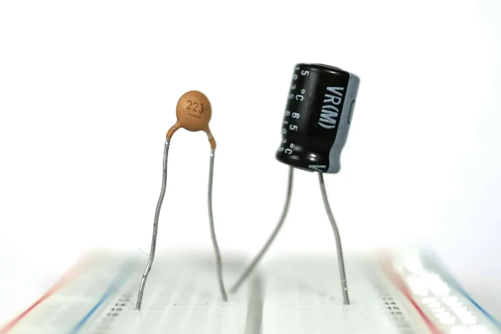
A capacitor is an electronic component that stores and releases electrical energy in a circuit. It consists of two conductive plates separated by an insulating material called a dielectric. When voltage is applied across the plates, electric charge accumulates on them, creating an electric field.
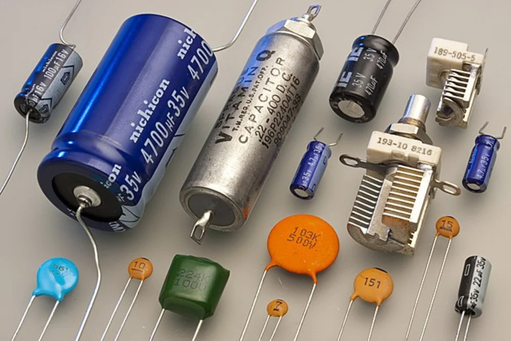
Capacitors are commonly used in electronic circuits for various purposes, including energy storage, filtering, coupling, and timing. They come in different types, sizes, and capacitance values to suit specific applications.
Deciphering The Numbers On A Capacitor
Deciphering the numbers stamped onto a capacitor might seem like decoding a cryptic message for those unfamiliar with electronic components. Yet, these seemingly random digits hold valuable information about the capacitor’s specifications and capabilities.
The numbers on a capacitor provide crucial information about its electrical characteristics. Here are the key types of information typically conveyed by these numbers:
Capacitance
Capacitance is the measure of a capacitor’s ability to store an electric charge. It is quantified in farads (F), although most capacitors are rated in microfarads (µF), nanofarads (nF), or picofarads (pF) due to the typical small size of the charges they handle. A higher capacitance value indicates a greater capacity to store charge.
Capacitance is a critical specification because it determines how much energy the capacitor can hold and, consequently, how it will perform in a circuit. For instance, in filtering applications, capacitors with different capacitance values will affect the frequency response of the filter.
Breakdown Voltage
Breakdown voltage, also known as working voltage, is the maximum voltage a capacitor can handle before it risks failure. When the voltage applied to a capacitor exceeds this limit, the dielectric material between the capacitor’s plates can become conductive, leading to a short circuit and potential damage to the capacitor and the circuit.
Breakdown voltage is typically marked in volts (V), and it’s crucial to choose a capacitor with a voltage rating higher than the maximum voltage it will encounter in the circuit. This ensures reliability and safety in electronic applications.
Temperature Coefficient
The temperature coefficient marking on a capacitor provides information about how its capacitance value changes with variations in temperature. This characteristic is crucial in applications where precise capacitance is required across a range of temperatures, as fluctuations can significantly impact the performance of an electronic circuit.
The temperature coefficient is typically expressed in parts per million per degree Celsius (ppm/°C). It indicates the rate of change of capacitance with temperature. For example, a capacitor with a temperature coefficient of ±100 ppm/°C will change its capacitance by ±100 parts per million for each degree Celsius change in temperature.
Dielectric Type Of Capacitor
In capacitors, the dielectric material plays a critical role in determining the component’s performance characteristics. Different dielectric materials have unique properties that affect the capacitor’s behavior in terms of temperature stability, equivalent series resistance (ESR), capacitance stability, and other performance metrics. Understanding the type of dielectric material used can help in selecting the right capacitor for a specific application.
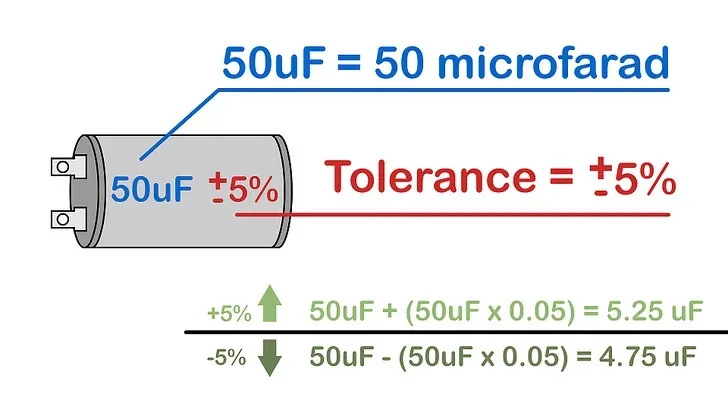
Tolerance
Tolerance indicates the permissible deviation from the capacitor’s stated capacitance value, usually expressed as a percentage. For example, a capacitor with a nominal capacitance of 100 µF and a tolerance of ±10% can have an actual capacitance between 90 µF and 110 µF.
Tolerance is important in applications requiring precise capacitance values, such as in timing circuits or tuned filters, where variations can significantly affect performance. Understanding tolerance helps in selecting the right capacitor to ensure the circuit functions correctly under various conditions.
Polarization
Polarization refers to the directionality of voltage that a capacitor can handle. Some capacitors, known as polarized capacitors, are designed to operate with a specific polarity. Electrolytic capacitors are a common example of polarized capacitors. They must be connected with the correct orientation, where the positive lead is connected to the higher potential and the negative lead to the lower potential.
Connecting a polarized capacitor incorrectly can result in leakage, reduced performance, or even destruction of the capacitor. Non-polarized capacitors, like ceramic or film capacitors, can be connected in either direction and are used in applications where polarity reversal might occur.
Understanding Color Codes: Older capacitors, particularly some ceramic capacitors, might use color codes to indicate values and tolerances. This system is similar to the color coding on resistors but less common in modern components.
How To Read The Numbers On A Capacitor?
1. Know the units of measurement
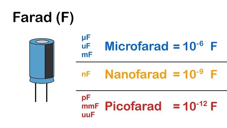
Understanding the units of measurement for capacitance is essential when working with capacitors. The base unit of capacitance is the farad (F), but this value is typically too large for most household and electronic circuits. Instead, capacitors are commonly labeled with smaller units, which include:
1 µF, uF, or mF = 1 microfarad = 10-6 farads. (Careful — in other contexts, mF is the official abbreviation for millifarads or 10-3 farads.)
1 nF = 1 nanofarad = 10-9 farads.
1 pF, mmF, or uuF = 1 picofarad = 1 micromicrofarad = 10-12 farads.
2. Read the capacitance value
When identifying the capacitance value on large capacitors, you may encounter various notations. Here are some guidelines to help you accurately interpret these markings:
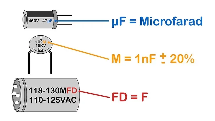
Ignore Capitalization Variations: The use of capital letters (e.g., “MF” instead of “mf”) does not alter the unit’s meaning. For instance, “MF” should not be interpreted as megafarads; it is just another way of expressing millifarads.
Consider “fd” as Farad: Terms like “fd” or “mmfd” are simply abbreviations for farads. “mmfd” is an older term equivalent to “mmf” (micromicrofarads), which means picofarads (pF).
Single-Letter Markings: Single-letter markings, such as “475m,” are typically found on smaller capacitors. These values are usually expressed in picofarads (pF).
Significant Figures: The first two digits represent the significant figures of the capacitance value.
Multiplier: The third digit indicates the number of zeros to add.
Unit Multiplier Letters:
“p” stands for picofarads (10-12 farads)
“n” stands for nanofarads (10-9 farads).
“µ” stands for microfarads (10-6 farads).
3. Look for a tolerance value
Check for the tolerance specification. Some capacitors indicate a tolerance, which represents the maximum expected deviation in capacitance from the stated value. While not critical for all circuits, precision may be necessary in some cases. For instance, a capacitor marked “6000uF +50%/-70%” could vary from 9000uF (6000uF + 50%) to 1800uF (6000uF – 70%).
If no percentage is provided, watch for a single letter after the capacitance value or on a separate line. This might signify a tolerance code, as explained below.
4. Check the voltage rating
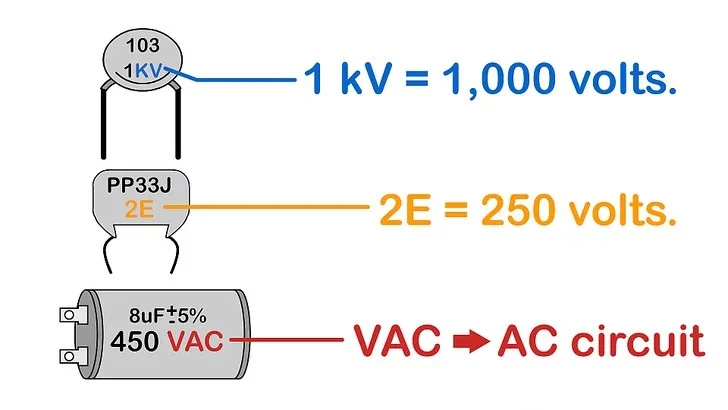
When space allows, capacitor manufacturers typically indicate the voltage on the capacitor body as a number followed by V, VDC, VDCW, or WV (indicating “Working Voltage”). This value signifies the maximum voltage the capacitor can withstand.
1 kV equals 1,000 volts.
If you suspect your capacitor employs a voltage code (such as a single letter or a combination of one digit and one letter), consult the voltage code reference below. If no symbol is present, reserve the capacitor for use in low-voltage circuits exclusively.
When dealing with AC circuits, ensure you select a capacitor rated for VAC. Avoid using a DC capacitor in an AC circuit unless you possess comprehensive knowledge of voltage rating conversion and safe capacitor usage in AC applications.
5. Look for a + or – sign
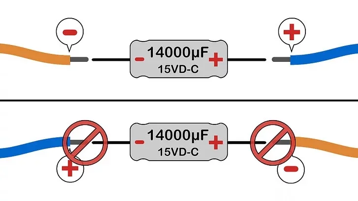
If you encounter one of these symbols adjacent to a terminal, it indicates polarization of the capacitor. Ensure that the positive (+) terminal of the capacitor is connected to the positive side of the circuit, as incorrect orientation could lead to a short circuit or even an explosion. In the absence of polarity indicators (+ or -), the capacitor can be oriented in either direction.
Some capacitors feature a colored bar or ring-shaped depression to denote polarity. Traditionally, this marker signifies the negative (-) terminal on aluminum electrolytic capacitors, typically resembling tin cans. Conversely, on tantalum electrolytic capacitors, usually compact in size, this mark indicates the positive (+) terminal. Disregard the polarity marker if it contradicts a + or – sign or if it appears on a non-electrolytic capacitor.
How Numerical Values Impact Capacitor Selection?
Capacitance Value
The capacitance value of a capacitor, measured in farads (F), microfarads (µF), nanofarads (nF), or picofarads (pF), indicates its ability to store electrical charge. This value impacts various applications. Higher capacitance values are used in power supplies to filter out low-frequency noise and ripple, ensuring a stable DC output.
In timing circuits, the capacitance value determines the frequency of oscillation, crucial for precise timing functions. Additionally, capacitance value affects signal integrity and noise reduction in coupling and decoupling applications, influencing the efficiency of data transmission and power distribution.
Voltage Rating
The voltage rating of a capacitor indicates the maximum voltage it can handle without breaking down. This value impacts safety and reliability. Using a capacitor with an insufficient voltage rating can lead to failure and potentially hazardous conditions. Therefore, selecting a capacitor with a voltage rating higher than the operating voltage ensures long-term reliability and prevents premature failure, enhancing the safety and stability of the electrical system.
Tolerance
Tolerance in capacitors represents the allowable deviation from the nominal capacitance value, typically expressed as a percentage. This characteristic impacts both precision and general applications. In precision applications such as filters and oscillators, where precise capacitance values are crucial, tight tolerance capacitors are essential to ensure accurate performance.
On the other hand, for less critical applications, capacitors with wider tolerances can be utilized, often at a lower cost, without compromising functionality.
Temperature Coefficient
The temperature coefficient of a capacitor describes how its capacitance changes with temperature variations. This characteristic impacts both stability and environmental suitability. Capacitors with low or near-zero temperature coefficients, such as NP0/C0G types, are used in applications requiring high stability over a wide temperature range.
Equivalent Series Resistance (ESR)
Equivalent Series Resistance (ESR) is the internal resistance of a capacitor when passing alternating current (AC). This characteristic impacts both efficiency and performance. Low ESR capacitors are preferred in high-frequency applications and power supplies because they reduce energy losses and heat generation. Capacitors with lower ESR provide better performance in high-speed digital and analog circuits, ensuring optimal functionality and reliability in demanding applications.
Dielectric Type
The dielectric material of a capacitor affects its characteristics, such as capacitance stability, ESR, and temperature performance. This impacts both application suitability and performance traits. Different dielectrics are suitable for various applications; for instance, ceramic capacitors (NP0/C0G) are used for high-stability applications, while electrolytic capacitors are used for bulk storage.
Selecting the right dielectric ensures that the capacitor meets specific performance requirements, such as low leakage current, high-frequency response, or high stability, thereby optimizing the capacitor’s functionality in its intended application.
Conclusion
Understanding the numbers on a capacitor is crucial for selecting the right component for specific electronic applications. These values provide essential information about capacitance, voltage rating, tolerance, temperature coefficient, ESR, and dielectric type, each impacting the capacitor’s performance and stability.
By understanding these numbers, engineers and technicians can make informed decisions, ensuring the reliability and effectiveness of their electronic designs, optimizing component selection, and achieving desired performance outcomes.