High-quality polarized capacitor manufacturer
Explore the world of polarized capacitors! Learn about their definition, functions, applications, types, and the differences between polarized and unpolarized capacitors.
What is a Polarized Capacitor?
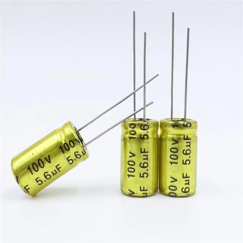
- Definition: A polarized capacitor is a type of capacitor that has a specific polarity – meaning it has a positive and a negative lead. This differs from unpolarized capacitors, which can be connected in any direction. In a polarized capacitor, connecting it incorrectly can result in damage or failure. This distinction is essential for its function in storing energy and controlling current flow.
- Polarized Capacitor Markings: To identify polarity, polarized capacitors have clear markings. The positive terminal is usually indicated with a longer lead, while the negative terminal might be marked with a stripe or a minus sign. Some designs, like “polarized capacitor smd” (surface-mount device) capacitors, may have special markings or notches.
- Example: A common polarized capacitor example is the electrolytic capacitor, which is often used in applications where large capacitance values are needed, such as in power supply filtering.
Function of a Polarized Capacitor
Energy Storage and Filtering
The function of polarized capacitor mainly involves storing electrical energy and releasing it when needed. This function is crucial for maintaining a steady voltage in circuits.
Voltage Regulation
Polarized capacitors are commonly used in power supplies to smooth out voltage fluctuations, helping to prevent sudden drops or surges. This ensures more stable current flow, which is essential for sensitive components.
Filtering AC and DC Signals
In AC/DC circuits, polarized capacitors are often used to filter and separate signals. They allow AC signals to pass while blocking DC, a function important in audio and power filtering applications.
Directional Usage
Due to their design, polarized capacitors must be installed with the correct orientation. This is referenced by the term polarized capacitor direction, which dictates that the positive lead is connected to the positive part of the circuit to prevent damage.
How Polarized Capacitors Work

- Working Principle: A polarized capacitor works by creating a separation of charge within its internal structure, which stores electrical energy. When a voltage is applied, ions in the electrolyte move toward the correct terminals, enabling the capacitor to hold and release energy.
- Polarized Capacitor Schematic: Diagrams, or polarized capacitor schematic, help illustrate how these capacitors should be positioned in circuits. This is especially useful for those using design software like LTspice for circuit simulation. Understanding this schematic layout can prevent incorrect installations.
- Voltage Ratings and Polarity: Each polarized capacitor has a maximum voltage rating. Exceeding this can cause the dielectric to break down, leading to potential leakage or failure. Ensuring the correct “polarized capacitor positive lead” connection prevents reverse polarity issues.
Applications of Polarized Capacitors

- Power Supply Filtering: A major polarized capacitor application is in power supply units to filter out unwanted AC noise from DC power. They stabilize the output voltage and reduce ripple in power circuits.
- Coupling and Decoupling: Polarized capacitors are frequently used for coupling, where they help pass desired signals while blocking DC components. They also serve as decoupling capacitors, isolating different parts of a circuit to prevent noise interference.
- In Audio and Signal Processing: In audio circuits, polarized capacitors are used to stabilize and filter signals, ensuring clean and stable audio output.
- AC Circuit Considerations: While primarily used in DC applications, polarized capacitors can sometimes be used in AC circuits if precautions are taken. However, when working with “polarized capacitor in ac circuit” applications, correct orientation and voltage handling are essential to avoid damage.
Polarized vs. Unpolarized Capacitors
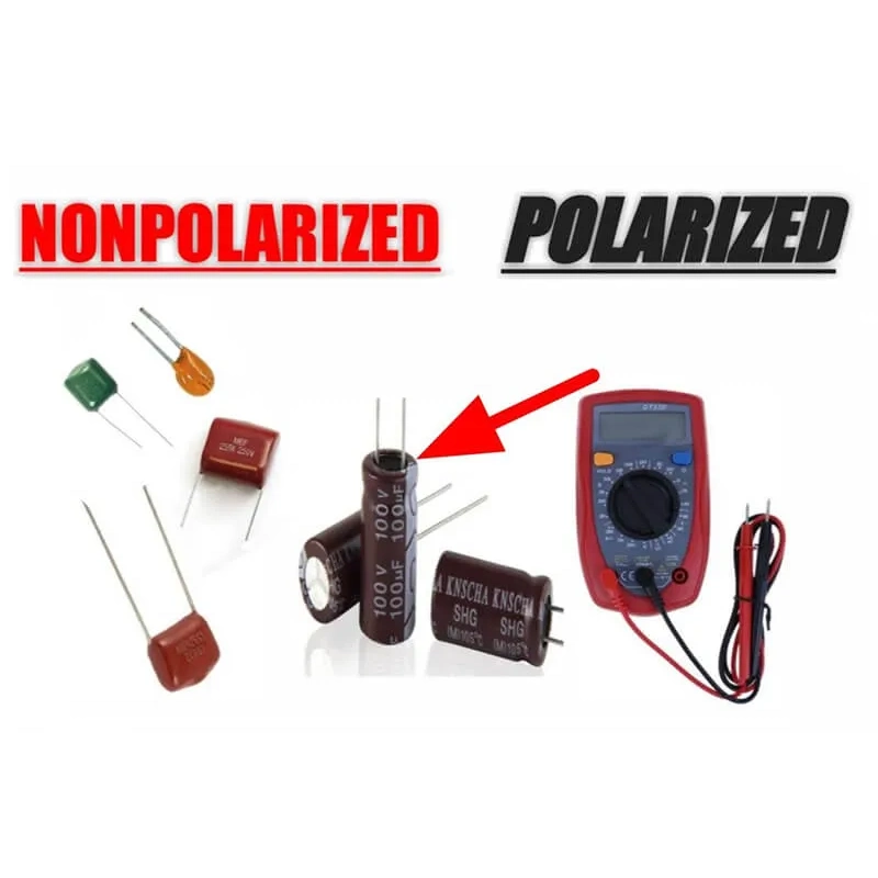
- Comparison of Features: The term polarized vs unpolarized capacitor refers to the fundamental difference in construction and application. Polarized capacitors are designed for DC circuits, where polarity is essential. In contrast, unpolarized capacitors, such as ceramic or film capacitors, are suitable for both AC and DC circuits without polarity restrictions.
- When to Use Each Type: Use polarized capacitors when high capacitance is needed in a DC circuit. For applications involving AC signals or where polarity cannot be easily managed, unpolarized capacitors are a better choice.
- Pros and Cons: Polarized capacitors offer higher capacitance in smaller sizes but come with limitations, such as sensitivity to reverse polarity. Unpolarized capacitors, while generally lower in capacitance, provide flexibility in AC circuits and are more durable against polarity issues.
Types of Polarized Capacitors
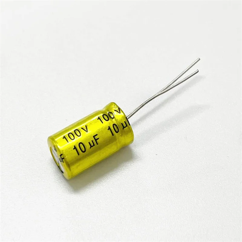
10uF Polarized Capacitor
The 10uF polarized capacitor is a common type, offering a balance of capacitance for medium-power applications. It’s ideal for power supply filtering and decoupling in audio circuits.
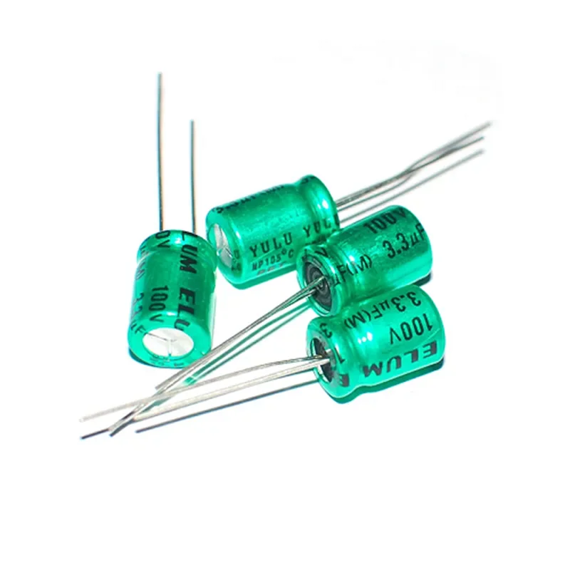
Polarized Capacitors in Series
Connecting polarized capacitors in series is often done to increase the voltage rating across the capacitors. When connected in series, the total capacitance decreases, but this arrangement allows handling of higher voltages safely.

Electrolytic Capacitors
One of the most common types of polarized capacitors, electrolytic capacitors offer high capacitance in a relatively small package, but they have voltage limitations and require correct polarity.
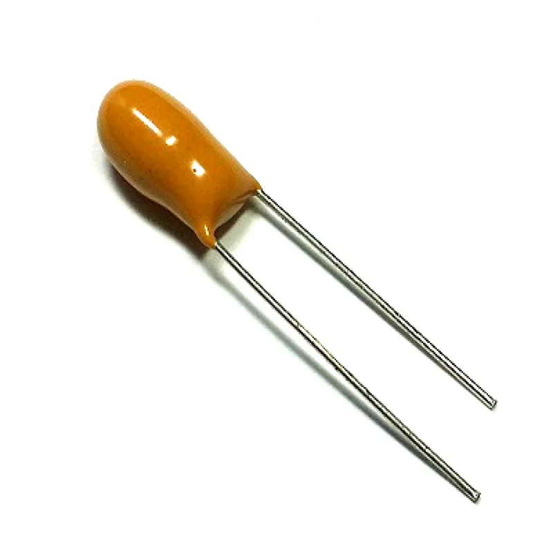
Tantalum Capacitors
Known for their reliability and stable performance, tantalum polarized capacitors are used in low-voltage applications. They’re sensitive to reverse polarity, so they must be connected correctly.
Polarized Capacitor FAQS
How to connect a polarized capacitor?
When connecting a polarized capacitor, ensure that the positive lead (often the longer lead) is connected to the positive voltage source. The negative lead, marked by a stripe or minus sign, should connect to the lower voltage or ground. Incorrect installation can lead to leakage, reduced lifespan, or capacitor failure.
How to identify a polarized capacitor?
Polarized capacitors are identifiable by markings. Look for the longer lead, which indicates the positive side, or a minus sign or stripe that marks the negative terminal. SMD polarized capacitors may have notches or specific colors to indicate polarity.
Which side of a polarized capacitor is positive?
The positive side of a polarized capacitor is often marked with a longer lead, while the negative side may have a stripe or minus sign. In schematic diagrams, this is typically shown clearly to prevent incorrect connections.
What happens if a polarized capacitor is connected backward?
Reversing the polarity can cause the capacitor to malfunction, leak, or even explode in severe cases. The electrolyte inside may degrade, causing heat and eventually failure, so always check polarity before installation.
What is the purpose of using polarized capacitors in series?
Connecting polarized capacitors in series increases the voltage handling capacity while decreasing total capacitance. This setup is useful in high-voltage applications where single capacitors cannot withstand the required voltage.
Can polarized capacitors be used in AC circuits?
While polarized capacitors are primarily for DC circuits, they can be used in AC circuits with specific configurations. They’re often paired with a diode or bridge rectifier to manage AC applications safely, though caution is advised to prevent damage.