This blog delves into the fundamental differences between two essential electronic components: inductors and capacitors. Often confused but operating on distinct principles, understanding their unique characteristics is crucial for anyone working with electrical circuits.
We will explore how each component stores and releases energy, their typical applications, and the impact of their respective properties—inductance and capacitance—on circuit behavior.
What is an Inductor?
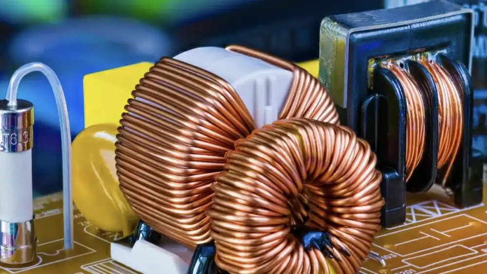
An inductor is a passive electronic component that stores energy in a magnetic field when electric current flows through it. Typically consisting of an insulated wire wound into a coil around a core (which can be air, ferrite, or iron), inductors oppose sudden changes in current.
This opposition is due to the phenomenon of electromagnetic induction, where a changing magnetic field induces a voltage that opposes the change in current. Inductors are crucial for applications like filtering, energy storage in power supplies, and in resonant circuits, where they can be combined with capacitors to select or generate specific frequencies.
What is a Capacitor?
A capacitor is a passive electronic component that stores energy in an electric field. It typically consists of two conductive plates separated by a dielectric (insulating) material. When a voltage is applied across the plates, an electric charge builds up on them, creating an electric field within the dielectric.
Capacitors oppose sudden changes in voltage and are widely used for filtering, smoothing power supplies, timing circuits, and energy storage, thanks to their ability to rapidly charge and discharge.
Inductor vs Capacitor

This blog delves into the fundamental differences between two essential electronic components: inductors and capacitors. Often confused but operating on distinct principles, understanding their unique characteristics is crucial for anyone working with electrical circuits.
Energy Storage Mechanism
Inductors store energy in a magnetic field. When current flows through the coil of an inductor, it generates a magnetic field around it. The strength of this field is directly proportional to the current flowing through the inductor. This stored energy can then be released back into the circuit when the current changes, attempting to maintain a constant current flow.
Capacitors, on the other hand, store energy in an electric field. They consist of two conductive plates separated by a dielectric (insulating) material. When a voltage is applied across the plates, charge accumulates on them, creating an electric field between the plates. The amount of charge stored is proportional to the applied voltage and the capacitance of the component.
Response to Current and Voltage Changes
Inductors resist changes in current. When the current flowing through an inductor attempts to change, the inductor generates a back electromotive force (EMF) that opposes this change. This property means that inductors tend to smooth out current fluctuations, acting like a “current flywheel” in a circuit.
Capacitors resist changes in voltage. When the voltage across a capacitor attempts to change, the capacitor charges or discharges to oppose this change. This characteristic makes capacitors effective at smoothing out voltage fluctuations, acting like a “voltage reservoir” that can supply or absorb charge as needed to maintain a steady voltage.
Impedance and Frequency Response
An inductor’s impedance (its opposition to AC current) increases with frequency. At low frequencies or DC, an ideal inductor acts like a short circuit (zero impedance), allowing current to pass easily. As frequency increases, its inductive reactance (XL=2πfL) rises, increasingly blocking higher-frequency AC signals.
A capacitor’s impedance decreases with frequency. At low frequencies or DC, an ideal capacitor acts like an open circuit (infinite impedance), blocking DC current. As frequency increases, its capacitive reactance (XC=1/(2πfC)) falls, allowing higher-frequency AC signals to pass more readily.
Ideal vs. Real-World Behavior
In an ideal model, an inductor is purely inductive and has zero resistance. However, real-world inductors have some inherent series resistance due to the wire used in the coil, and parasitic capacitance between turns. These non-ideal characteristics become more significant at higher frequencies, affecting the inductor’s performance and introducing energy losses.
Similarly, an ideal capacitor has no resistance and perfect insulation between plates. Real capacitors, however, exhibit a small equivalent series resistance (ESR) and equivalent series inductance (ESL), as well as leakage current through the dielectric. These imperfections can lead to energy dissipation and affect the capacitor’s ability to filter or store charge effectively, especially at high frequencies.
Common Applications
Inductors are frequently used in power supplies for filtering and smoothing current, in resonant circuits for tuning radio frequencies, and in switched-mode power supplies for energy storage and voltage conversion. They are also found in chokes to block AC signals while allowing DC to pass, and in transformers where mutual inductance is utilized for voltage transformation.
Capacitors are ubiquitous in electronic circuits, used for decoupling and bypassing to stabilize power lines, in timing circuits for setting delays, and in filters to block DC while passing AC. They are also essential components in resonant circuits alongside inductors, and in energy storage applications like flash photography and defibrillators due to their ability to discharge rapidly.
Energy Storage and Release
Capacitor: The energy stored in a capacitor (Ec) is given by Ec = 1/2CV². When a capacitor discharges, this stored energy is released back into the circuit.
Inductor: The energy stored in an inductor (EL) is EL = 1/2Li². When the current through an inductor changes, the stored magnetic energy is either absorbed or released.
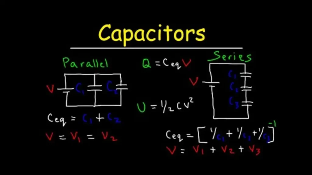
Series and Parallel Combinations
Series: When a capacitor and an inductor are in series, the total impedance Z = √[(XL – Xc)² + R²] (if there is also resistance in the circuit). The resonant frequency (fr) of a series LC circuit is given by fr = 1/(2π√LC).
Parallel: In a parallel combination of a capacitor and an inductor, the equivalent impedance and the behavior of the circuit are different. The resonant frequency in a parallel LC circuit also has a different formula and behavior compared to the series case.
Inductor vs Capacitor Applications
Capacitor Applications
For power supply filtering, capacitors are effective in smoothing out DC voltage ripple. In rectified power supplies, they charge during peaks and discharge during valleys, reducing variations. Different types of capacitors are used as needed. In amplifiers, they couple and decouple AC signals between stages. Coupling capacitors pass audio signals while blocking DC bias in audio amplifiers. Decoupling capacitors near components supply current during amplification, reducing noise. Capacitors are essential in RC oscillator timing circuits. The RC time constant controls the charge and discharge, determining the oscillation frequency. This is used in clock generation and other timing applications.
Inductor Applications
Inductors are used in switching power supplies for energy storage and transfer. During the on-time of the switch, the current through the inductor creates a magnetic field that stores energy. When the switch is off, the inductor releases the energy to the load. They are combined with capacitors to form LC filters. In low-pass LC filters, the reactive properties of the inductor and capacitor attenuate high-frequency signals. In RF applications, inductors are used in tuning circuits. In radio receivers, variable capacitors can be used to adjust the LC resonant circuit to match the frequency of the desired radio station for selection.
Inductor and Capacitor in Parallel
Connecting inductors and capacitors in parallel fundamentally alters their combined electrical properties, leading to applications vastly different from their individual uses. This configuration is particularly important in resonant circuits, where their opposing reactive properties can cancel each other out at a specific frequency, creating a powerful frequency-selective network.
Here’s how inductors and capacitors behave when connected in parallel:
- Total Inductance/Capacitance: When inductors are connected in parallel, their individual inductances combine reciprocally, similar to how resistors combine in parallel, resulting in a smaller total inductance. For capacitors, when connected in parallel, their individual capacitances simply add up, yielding a larger total capacitance.
- Resonance (Parallel LC Circuit): A parallel combination of an inductor and a capacitor forms a resonant circuit, also known as a tank circuit. At a specific frequency, called the resonant frequency (fr=1/(2πLC
)), the inductive reactance (XL) becomes equal in magnitude to the capacitive reactance (XC), causing them to cancel each other out.
- Impedance at Resonance: At its resonant frequency, a parallel LC circuit ideally presents a very high (theoretically infinite) impedance to the external circuit. This high impedance means it will significantly impede current flow at that specific frequency, effectively acting as an open circuit for the resonant frequency, while allowing other frequencies to pass more easily.
- Current Behavior at Resonance: Although the total current drawn from the source at resonance is very low due to high impedance, there is a large circulating current between the inductor and capacitor. Energy continuously oscillates between the inductor’s magnetic field and the capacitor’s electric field within the tank circuit, with minimal energy drawn from the external source.
- Applications: Parallel LC circuits are widely used as notch filters to block or attenuate a specific frequency, such as unwanted noise. They are also crucial in radio frequency (RF) circuits for tuning, as oscillator circuits to generate specific frequencies, and in induction heating applications where high circulating currents are utilized.
Inductor and Capacitor in Series
Connecting inductors and capacitors in series also fundamentally alters their combined electrical properties, creating different circuit behaviors compared to their parallel counterparts. This configuration is likewise crucial in resonant circuits, where their opposing reactive properties can cancel each other out at a specific frequency, leading to distinct frequency-selective characteristics.
Here’s how inductors and capacitors behave when connected in series:
- Total Inductance/Capacitance: When inductors are connected in series, their individual inductances simply add up, resulting in a larger total inductance (Ltotal=L1+L2+…). For capacitors, when connected in series, their individual capacitances combine reciprocally, similar to how resistors combine in parallel, yielding a smaller total capacitance (1/Ctotal=1/C1+1/C2+…).
- Resonance (Series LC Circuit): A series combination of an inductor and a capacitor also forms a resonant circuit. At the resonant frequency (fr=1/(2πLC
)), the inductive reactance (XL) again becomes equal in magnitude to the capacitive reactance (XC), causing them to cancel each other out. This shared resonant frequency is a key characteristic for both series and parallel LC circuits.
- Impedance at Resonance: In contrast to the parallel configuration, a series LC circuit ideally presents a very low (theoretically zero) impedance at its resonant frequency. This low impedance means it will readily allow current flow at that specific frequency, effectively acting as a short circuit for the resonant frequency, while impeding other frequencies.
- Voltage Behavior at Resonance: Although the total impedance across the series LC circuit is minimal at resonance, large individual voltages can develop across the inductor and capacitor, even with a small applied voltage. These voltages, VL and VC, will be equal in magnitude and 180 degrees out of phase, effectively canceling each other out across the series combination.
- Applications: Series LC circuits are widely used as band-pass filters to allow or pass a specific range of frequencies while attenuating others, common in radio tuners. They are also employed in power factor correction circuits to improve efficiency by compensating for reactive power, and in oscillator feedback networks to establish the desired operating frequency.
Inductor and Capacitor Equations
Understanding the fundamental equations governing inductors and capacitors is crucial for analyzing and designing AC and DC circuits. These equations describe their unique relationships between voltage, current, frequency, and energy storage, highlighting why they behave so differently.
Here are the key equations for inductors and capacitors:
Inductor Equations:
- Voltage-Current Relationship: VL=LdtdIL This equation states that the voltage across an inductor (VL) is proportional to the inductance (L) multiplied by the rate of change of current (dIL/dt) flowing through it. This shows the inductor’s opposition to sudden current changes.
- Inductive Reactance: XL=2πfL Inductive reactance (XL) is the opposition an inductor presents to alternating current (AC). It is directly proportional to the frequency (f) of the AC signal and the inductance (L). Measured in ohms (Ω).
- Energy Stored: EL=21LI2 The energy (EL) stored in an inductor’s magnetic field is proportional to half the inductance (L) multiplied by the square of the current (I) flowing through it. Measured in joules (J).
Capacitor Equations:
- Voltage-Charge Relationship: Q=CVC The charge (Q) stored on a capacitor’s plates is directly proportional to its capacitance (C) and the voltage (VC) across it.
- Current-Voltage Relationship: IC=CdtdVC This equation shows that the current (IC) through a capacitor is proportional to the capacitance (C) multiplied by the rate of change of voltage (dVC/dt) across it. This illustrates the capacitor’s opposition to sudden voltage changes.
- Capacitive Reactance: XC=2πfC1 Capacitive reactance (XC) is the opposition a capacitor presents to AC. It is inversely proportional to the frequency (f) of the AC signal and the capacitance (C). Measured in ohms (Ω).
- Energy Stored: EC=21CV2 or EC=21CQ2 or EC=21QV The energy (EC) stored in a capacitor’s electric field is proportional to half the capacitance (C) multiplied by the square of the voltage (V) across it (or related to charge Q). Measured in joules (J).
How to Choose Inductors and Capacitors
Choosing the right inductor or capacitor for a specific circuit is a critical step in electronic design, influencing performance, efficiency, and reliability. It’s not just about selecting a value, but also considering various parasitic effects and environmental factors that can impact the component’s behavior in the real world.
When selecting these passive components, designers must balance theoretical requirements with practical limitations. The ideal behavior described in textbooks rarely translates perfectly to real-world components, which possess inherent resistances, inductances, and capacitances that become more prominent at higher frequencies or under specific operating conditions.
How to Choose an Inductor
Selecting an inductor involves evaluating several key parameters to match the component to the circuit’s needs:
- Inductance Value (L): This is the primary parameter, determined by circuit calculations (e.g., filter cutoff frequency, switching converter ripple current). It’s crucial to select a value that provides the desired performance for the application.
- Current Rating (Saturation Current, RMS Current):
- Saturation Current (Isat): The DC current at which the inductor’s inductance drops by a specified percentage (e.g., 20% or 30%) due to core saturation. It must be higher than the peak current the circuit will experience.
- RMS Current (Irms): The maximum continuous current the inductor can handle without exceeding its specified temperature rise due to winding resistance. It should be greater than the maximum continuous current in the circuit.
- DC Resistance (DCR): The resistance of the wire windings. A lower DCR means less power loss and higher efficiency, especially in power applications.
- Self-Resonant Frequency (SRF): The frequency at which the inductor’s parasitic capacitance resonates with its inductance, causing it to act as a resistor, then a capacitor beyond this frequency. The SRF should be significantly higher (e.g., 5-10 times) than the operating frequency of the circuit.
- Q Factor (Quality Factor): A dimensionless parameter indicating the inductor’s efficiency at a specific frequency. A higher Q factor means lower losses and better performance, especially in resonant circuits.
- Tolerance: The permissible deviation from the nominal inductance value. Tighter tolerances are required for precision applications like filters and oscillators.
- Physical Size and Mounting: Must fit within the available PCB space and be compatible with the assembly method (e.g., surface mount device (SMD) or through-hole).
- Core Material: Influences inductance, saturation characteristics, and frequency response (e.g., air core for high frequency, ferrite for power applications).
How to Choose a Capacitor
Choosing a capacitor also requires careful consideration of various specifications beyond just capacitance:
- Capacitance Value (C): This is the fundamental requirement, derived from circuit calculations (e.g., filter cutoff frequency, timing constant, energy storage).
- Voltage Rating (Vrated): The maximum DC voltage (or peak AC voltage) that can be continuously applied across the capacitor without damage. A common guideline is to choose a capacitor with a voltage rating at least 1.5 to 2 times the maximum expected voltage in the circuit.
- Dielectric Material and Type: The material between the plates significantly impacts performance.
- Ceramic: Good for high-frequency, low ESR/ESL (MLCCs). Class 1 ceramics (C0G/NP0) offer high stability, while Class 2 (X7R, Z5U, Y5V) offer higher capacitance but with temperature and voltage dependency.
- Electrolytic (Aluminum, Tantalum): High capacitance in a small size, suitable for power supply filtering and energy storage. They are polarized and have higher ESR/ESL and limited lifespan.
- Film (Polyester, Polypropylene): Good stability, low loss, non-polarized, often used in timing, resonant, and audio circuits.
- Equivalent Series Resistance (ESR): The total resistive component within the capacitor. Lower ESR is crucial for high-frequency filtering, power supply ripple reduction, and applications where heat dissipation is a concern.
- Equivalent Series Inductance (ESL): The parasitic inductance of the capacitor, which becomes significant at higher frequencies, causing the capacitor to self-resonate and act inductively above its SRF.
- Tolerance: The permissible deviation from the nominal capacitance value. Precision applications like filters or timing circuits often require tighter tolerances.
- Temperature Characteristics: How the capacitance value changes with temperature. This is especially important for ceramic capacitors.
- Leakage Current: A small DC current that flows through the dielectric when voltage is applied. Lower leakage current is desirable for long-term energy storage and battery-powered applications.
- Physical Size and Mounting: Similar to inductors, the capacitor must fit the PCB layout and assembly requirements.
Conclusion
Capacitors and inductors are both essential components in electronics, with distinct properties and behaviors. Their differences in energy storage, electrical response in DC and AC circuits, impedance, and phase shift make them suitable for a wide range of applications.
Understanding how they interact in series and parallel combinations further expands the possibilities for circuit design. Whether you’re dealing with a simple power supply circuit or a complex radio frequency system, a clear understanding of capacitor vs inductor is a must-have skill.