Film capacitors are essential components in electronic circuits, offering a wide range of functions and applications. When working with film capacitors, understanding how to read and decipher their markings is crucial for selecting the right capacitor for your specific needs.
Join us as we delve into the nuances of reading film capacitor labels and learn how to decode the information they contain.
What Is Film Capacitor
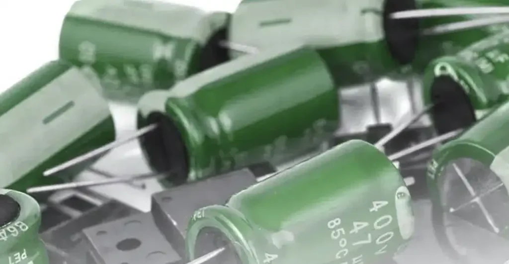
Film capacitors, also known as plastic film capacitors, film dielectric capacitors, or polymer film capacitors, are a type of capacitor that utilizes a thin plastic film as the dielectric insulator. This film separates two conductive plates, typically made from aluminum foil, to store electrical energy.
Here’s a breakdown of key characteristics of film capacitors:
Dielectric Material:
- The plastic film acts as the insulator, preventing current flow between the conductive plates.
- Common film materials include polyester (Mylar), polypropylene (PP), polyethylene terephthalate (PET), and polystyrene (PS).
- Each film type offers varying properties like temperature tolerance, stability, and cost.
Construction:
- Film capacitors are generally constructed by winding or layering the plastic film with the metal electrodes.
- The assembly is then encased in a protective housing to shield it from the environment.
Properties:
Film capacitors are known for their:
- Stability: They offer stable capacitance values over a wide range of temperatures.
- High Insulation Resistance: The plastic film provides excellent resistance to current leakage.
- Low Self-Inductance: They have minimal opposition to changes in current flow, making them suitable for high-frequency applications.
- Self-healing: Some film types (like polypropylene) have a self-healing property. If a voltage surge creates a small defect in the film, it can vaporize the surrounding metal, effectively healing the gap.
Cracking the Code: Film Capacitor Markings
Capacitance Value: The capacitance value of a film capacitor is expressed in units of farads (F) or microfarads (μF). Typically, the capacitance value is marked directly on the capacitor body, often using alphanumeric codes. For example, a marking of “473” indicates a capacitance value of 47,000 pF, which is equivalent to 0.047 μF.
Tolerance Rating: Film capacitors come with a tolerance rating that indicates the permissible deviation from the specified capacitance value. Common tolerance values include ±5%, ±10%, or ±20%. This information is usually denoted by a letter code following the capacitance value. For example, a marking of “473J” indicates a capacitance value of 47,000 pF with a tolerance of ±5%.
Voltage Rating: The voltage rating specifies the maximum voltage that the capacitor can safely handle. This information is crucial for ensuring the capacitor can withstand the voltage present in the circuit. The voltage rating is often specified in volts (V) and is marked on the capacitor body. For example, a marking of “250V” indicates a voltage rating of 250 volts.
Dielectric Material: Film capacitors use various dielectric materials such as polyester (PET), polypropylene (PP), polycarbonate (PC), and more. While the dielectric material may not always be explicitly labeled on the capacitor, the material type is critical for understanding the capacitor’s performance characteristics, temperature stability, and reliability.
Manufacturer Code: Some film capacitors include a manufacturer code or logo that identifies the company that produced the capacitor. This information can be valuable for quality control, identification of the capacitor source, and tracing the capacitor’s specifications.
Temperature Rating: Film capacitors may have temperature ratings that indicate the range of temperatures at which the capacitor can operate effectively. This information is essential for selecting capacitors suitable for specific environmental conditions or applications where temperature fluctuations may occur.
Operating Frequency: In certain cases, film capacitors designed for specific applications, such as high-frequency circuits, may include markings or specifications related to their optimal operating frequency range. Understanding the operating frequency capabilities of the capacitor ensures proper performance in the intended circuit.
How to Test Film Capacitor With Multimeter
To test a film capacitor with a multimeter, follow these steps:
First, make sure your multimeter is set to the capacitance (Cap or µF) setting. Some multimeters may also have a specific setting for film or electrolytic capacitors, so you can use that if available.
Turn off and unplug the device that the capacitor is connected to, for safety reasons.
Disconnect the film capacitor from the circuit. To do this, locate the capacitor and its associated leads or terminals. Use a screwdriver to loosen and remove any screws that may be holding the capacitor in place, if necessary. Carefully twist and pull the leads or terminals apart to disconnect the capacitor from the circuit.
Set up your multimeter as follows: Attach one probe (preferably the red one) to the terminal or lead that was previously connected to the positive (+) terminal of the capacitor. Attach the other probe (the black one, or the one with the ground symbol) to the terminal or lead that was connected to the negative (-) terminal of the capacitor. Make sure the probes are securely attached and not accidentally touching each other.
Press the “Cap” or “Continuity” button on your multimeter if it has one. This will activate the capacitance measurement mode.
Read the capacitance value on the multimeter display. The value shown should be close to the rated capacitance of the film capacitor, assuming the capacitor is in good working condition. If the displayed value is significantly higher or lower than the rated capacitance, it may indicate a faulty or damaged capacitor.
If your multimeter does not have a “Cap” or “Continuity” button, hold the probes in place and wait for a few seconds. Some multimeters may take a bit of time to measure the capacitance. After a few seconds, the multimeter should display the capacitance value or indicate whether the capacitor is faulty (usually with a “low” or “open” symbol).
If you’re uncertain about the results, consult a repair manual or technical expert to further diagnose the issue with the film capacitor.
Remember to always observe safety precautions when working with electrical components, and to never test a capacitor with a multimeter without first discharging it or disconnecting it from the power source.
If you are dealing with high-voltage capacitors, it is advisable to use a capacitance megohm meter or capacitor checker, as regular multimeters might not be suitable for high-voltage capacitors. Always consult the manufacturer‘s guidelines for specific instructions and recommendations.
Conclusion
Film capacitors are versatile components that play a crucial role in various electronic applications. By learning how to interpret and read the markings on film capacitors, you gain insight into their key specifications, allowing you to make informed decisions when selecting capacitors for your projects.
Whether you’re designing circuits, troubleshooting electronic systems, or simply exploring the world of electronics, understanding capacitor markings empowers you to harness the full potential of film capacitors in your endeavors.