Electronic components are the building blocks of modern technology, found in everything from smartphones to spacecraft. Understanding how to read these components is essential for hobbyists, students, and professionals alike.
Whether you’re repairing a device or designing a new circuit, being able to interpret electronic components is a valuable skill.
In this guide, we’ll explore the basics of reading electronic components, from identifying different types to deciphering component markings and datasheets.
Electronic Components Definition
Before diving into the specifics of reading electronic components, it’s crucial to understand what they are and their significance in electronic systems. Electronic components are individual devices or elements that are used to build electronic circuits. These components can be broadly classified into two categories: passive and active.
Understanding Electronic Component Types

Passive Electronic Components
Passive electronic components do not require a power source to operate and primarily manipulate electrical energy. The most common types of passive components include resistors, capacitors, and inductors.
Resistors
Resistors are components that restrict the flow of electrical current. They are often color-coded to indicate their resistance value.
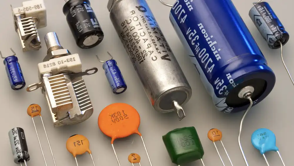
Capacitors
Capacitors store and release electrical energy. They are marked with capacitance values and voltage ratings.
Inductors
Inductors store energy in a magnetic field when current flows through them. They are identified by their inductance value.
Active Electronic Components
Active electronic components require an external power source to function and can amplify or switch electronic signals. Some of the primary active components include diodes, transistors, and integrated circuits (ICs).
Diodes
Diodes allow current to flow in one direction and block it in the opposite direction. They are often marked with polarity indicators.
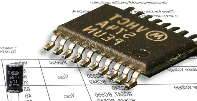
Transistors
Transistors are semiconductor devices used for amplification and switching of electronic signals. They come in various types such as bipolar junction transistors (BJTs) and field-effect transistors (FETs).
Integrated Circuits
Integrated circuits are complex assemblies of electronic components fabricated on a single semiconductor substrate. They can contain thousands or even millions of individual components.
Reading Electronic Component Markings
Understanding the markings on electronic components is essential for identifying their specifications and characteristics.
Resistor Color Codes
Resistors are often marked with colored bands that represent their resistance value and tolerance.
Capacitor Markings
Capacitors are labeled with codes or numbers indicating their capacitance, voltage rating, and sometimes their tolerance.
Diode Polarity
Diodes typically have markings indicating their polarity, such as a band or arrow.
How to Read Electronic Component Datasheet
Reading an electronic component datasheet is essential for understanding the specifications, characteristics, and applications of the component.
Here’s a step-by-step guide on how to read an electronic component datasheet:
- Identify the Component: Start by identifying the specific electronic component for which you have the datasheet. Note the part number, manufacturer name, and any relevant markings on the component.
- Locate the Datasheet: Obtain the datasheet from a reliable source such as the manufacturer’s website, distributor’s website, or a specialized electronic component database.
- Review the Overview: Begin by reading the overview section, which provides a brief description of the component, its purpose, functionality, and key features. This section gives you a general understanding of what the component is designed to do.
- Understand Electrical Characteristics: Pay close attention to the electrical characteristics section, which outlines the component’s electrical properties. This includes parameters such as voltage ratings, current ratings, resistance values, capacitance values, and frequency characteristics.
- Check Absolute Maximum Ratings: Review the absolute maximum ratings section to understand the maximum voltage, current, power, temperature, and other environmental conditions that the component can safely withstand without damage. Ensure that your operating conditions fall within these limits.
- Examine Pin Configuration: Study the pin configuration diagram or table to understand the pinout of the component. This indicates the function of each pin and its corresponding connection in a circuit.
- Analyze Operating Conditions: Understand the recommended operating conditions for the component, including voltage supply range, temperature range, and humidity range. Ensure that your application meets these conditions for optimal performance.
- Review Application Circuits: Examine the application circuits section to see typical usage scenarios and recommended circuit configurations for the component. This provides insights into how to integrate the component into your circuit design effectively.
- Check Packaging Information: Understand the type of package used for the component, such as through-hole, surface mount, or ball grid array (BGA), along with details on tape and reel specifications for packaging and handling.
- Verify Compliance and Certification: Check whether the component complies with industry standards, regulations, and certifications such as RoHS compliance, REACH compliance, and CE certification.
- Note Ordering Information: Finally, note the ordering information, including part numbers, package options, quantities, and lead times, if you plan to purchase the component.
How to Read Circuit Boards – Standards for Electronic Symbols
Reading circuit boards can be a valuable skill for understanding electronic devices and troubleshooting electrical issues.
Here’s a step-by-step guide on how to read circuit boards:
Identify Electronic Components: Familiarize yourself with common electronic components such as resistors, capacitors, diodes, transistors, integrated circuits (ICs), connectors, and traces (wires). Each component serves a specific function in the circuit.
Component Identification: Components on circuit boards are typically labeled with codes or markings indicating their values or specifications. For instance, resistors often have colored bands indicating their resistance value, capacitors may have alphanumeric codes indicating capacitance and voltage ratings, and ICs usually have part numbers.
Trace Follow-Up: Traces are the copper pathways on the circuit board that connect components. Follow these traces to understand the flow of current through the circuit and to identify connections between components.
Schematic Diagrams: Refer to schematic diagrams if available. These diagrams represent the circuit’s components and connections in a graphical format, making it easier to understand the circuit’s functionality. Components are represented by symbols, and lines indicate connections between them.
Orientation and Alignment: Pay attention to the orientation and alignment of components on the circuit board. Certain components, such as diodes and electrolytic capacitors, have polarity markings that must be observed during installation.
Power and Ground Connections: Identify power and ground connections on the circuit board. These connections provide the necessary voltage and reference points for the circuit to operate correctly.
Identify Input and Output Connections: Determine the input and output connections of the circuit. Inputs are where signals or power are supplied to the circuit, while outputs are where the circuit delivers its results or signals.
Study the Layout: Analyze the layout of the circuit board. Components are often arranged logically based on their functions and connections. Observing this layout can provide insights into the circuit’s design and operation.
Test Points: Some circuit boards may include test points or pads for diagnostic purposes. These points allow technicians to measure voltages or signals at specific locations on the board, aiding in troubleshooting.
Practice and Patience: Reading circuit boards requires practice and patience. Start with simple circuits and gradually work your way up to more complex ones. Over time, you’ll become more proficient at interpreting circuit board layouts and understanding their functionality.
By following these steps and continually practicing, you can develop the skills needed to effectively read and understand circuit boards.
How to Read Date Code on Electronic Components
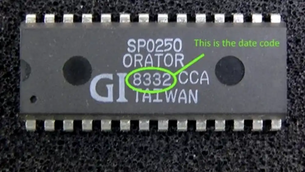
Reading date codes on electronic components can be crucial for determining their age and lifespan. Here’s a general guide on how to read date codes:
Understand Date Code Formats: Date codes can vary depending on the manufacturer and type of component. Common formats include alphanumeric codes, numeric codes, or codes with specific symbols. Familiarize yourself with the format used by the manufacturer of the component you’re examining.
Identify the Date Code: Locate the date code on the electronic component. It is typically printed or stamped directly on the component’s body or packaging. The location of the date code may vary depending on the type of component.
Decode the Date Code: Once you’ve found the date code, decode it according to the format used by the manufacturer. Here are some common methods used in date codes:
- Alphanumeric Codes: Some manufacturers use alphanumeric codes where letters represent months (e.g., A for January, B for February, etc.) and numbers represent years. For example, a date code of “A21” might indicate January 2021.
- Numeric Codes: In numeric date codes, the first one or two digits often represent the year, while the subsequent digits represent the week or month of production. For example, a date code of “215” might indicate the 15th week of 2021.
- Symbolic Codes: Some manufacturers use symbols or combinations of symbols to represent dates. These symbols may need to be cross-referenced with a decoding table provided by the manufacturer.
Consider Context: Take into account the context in which the component is used. For example, if you’re examining a circuit board, the date code may provide insight into the age of the board and the potential need for maintenance or replacement.
Consult Manufacturer Documentation: If you’re unsure about how to decode the date code, consult the manufacturer’s documentation or website. Many manufacturers provide information on how to interpret date codes for their components.
Verify with Multiple Components: If possible, verify the date code by checking multiple components from the same batch or production run. This can help confirm the accuracy of the decoding process and ensure consistency across components.
Consider Shelf Life and Storage Conditions: Keep in mind that even if you can accurately read the date code, the component’s age may not necessarily reflect its remaining lifespan. Factors such as shelf life and storage conditions can also impact the component’s reliability and performance.
By following these steps and understanding the format used in date codes, you can effectively read and interpret date codes on electronic components. This information can be valuable for assessing the age and condition of components and making informed decisions regarding maintenance or replacement.
How to Read Resistor Color Code
Understanding resistor color codes is a fundamental skill for anyone delving into the world of electronics. Resistor color codes, represented by bands on the body of resistors, hold vital information about their resistance values, which is crucial for designing and troubleshooting electronic circuits.
Decoding the Color Bands:
The process of reading resistor color codes can be broken down into simple steps:
- Observation: Start by observing the colored bands on the resistor body. These bands typically consist of four or five distinct colors.
- Identification: Each color band represents a specific number. It’s essential to identify these significant colors accurately.
- Matching: Match the colors with their corresponding numbers and positions. The order of the bands matters, and you’ll read them from left to right.
- Reading the Values: Now, read the numbers indicated by the colored bands. The value of the resistor can be determined by the sequence of these numbers.
Let’s take a closer look at what each color band signifies:
- First Band (Brown): This represents the first digit of the resistance value. For instance, if the resistor is 1k ohms, the first digit is 1.
- Second Band (Black): This band signifies the second digit of the resistance value. In the case of 1k ohms, the second digit is 0.
- Third Band (Red): Acting as the multiplier band, this determines the magnitude by which the first two digits should be multiplied. For instance, red represents a multiplier value of 100, hence amplifying the value significantly.
Example:
For a 1k ohm resistor, the color code would be brown – black – red.
5-Band Resistors:
Some resistors come with an additional band, often indicating tolerance. A 5-band resistor, such as one with a 1% tolerance, offers a more precise resistance value. The first three bands determine the value, while the fourth band ensures accuracy by denoting tolerance.
Application in Circuits:
1k ohm resistors, with their color code of brown-black-red, are ubiquitous in electronic circuits. They play a crucial role in regulating current flow while maintaining desired voltage levels.
Exploring Further:
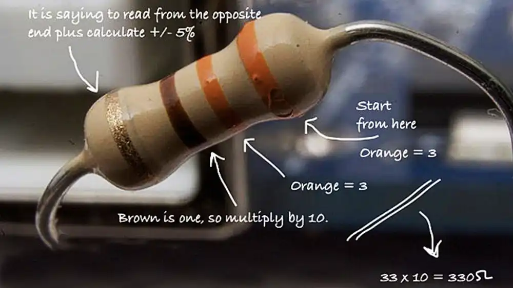
What about a 3.9k ohm resistor?
- First Band (Orange): Represents the first digit, which is 3.
- Second Band (White): Indicates the second digit, which is 9.
- Third Band (Red): Multiplier band, with a value of 100.
- Fourth Band (Brown): Tolerance band, indicating the standard tolerance level.
Mastering resistor color codes is essential for anyone working with electronic circuits. It simplifies the selection of resistors for specific applications, enabling efficient and accurate circuit design and troubleshooting. So, next time you encounter a resistor, remember to decode its colorful bands to unveil its resistance value and ensure your circuits function flawlessly.
Where to Start Reading Circuit Boards
When starting to read circuit boards, it’s helpful to begin with a systematic approach to gradually build your understanding.
Here’s a guide on where to start:
Basic Component Identification: Familiarize yourself with the most common electronic components found on circuit boards, such as resistors, capacitors, diodes, transistors, integrated circuits (ICs), and connectors. Learn to recognize these components visually and understand their basic functions.
Component Labels and Markings: Pay attention to the labels and markings on components. Resistors often have color bands indicating their resistance value, capacitors may have alphanumeric codes indicating capacitance and voltage ratings, and ICs usually have part numbers. Understanding these markings will help you interpret the specifications of each component.
Orientation and Polarity: Learn to identify the orientation and polarity of components. Components like diodes, electrolytic capacitors, and ICs have specific orientations that must be observed during installation. Polarity markings such as (+) and (-) symbols or notch indicators help ensure correct placement.
Trace Following: Start tracing the copper pathways, or traces, on the circuit board. Follow the traces to understand how components are connected and how current flows through the circuit. This will give you insight into the overall circuit topology and help you identify key connections.
Schematic Diagrams: If available, refer to schematic diagrams of the circuit. Schematics provide a graphical representation of the circuit’s components and connections, making it easier to understand the circuit’s design and functionality. Study the symbols used in schematics to interpret the circuit layout.
Power and Ground Connections: Identify the power and ground connections on the circuit board. These connections provide the necessary voltage and reference points for the circuit to operate correctly. Understanding where power enters the circuit and how it is distributed is essential for troubleshooting and analysis.
Input and Output Connections: Determine the input and output connections of the circuit. Inputs are where signals or power are supplied to the circuit, while outputs are where the circuit delivers its results or signals. Understanding the input-output relationships helps you grasp the purpose and operation of the circuit.
Layout Analysis: Analyze the layout of the circuit board. Observe how components are arranged and grouped together. Components are often placed strategically based on their functions and connections. Understanding the layout provides insights into the circuit’s design and helps you identify critical components and pathways.
Test Points and Diagnostic Features: Look for test points or diagnostic features on the circuit board. These may include pads or connectors specifically designed for testing and troubleshooting purposes. Utilizing test points can help you measure voltages or signals at various points on the board, aiding in diagnostics and analysis.
Practice and Exploration: Finally, practice reading circuit boards regularly. Start with simple circuits and gradually work your way up to more complex ones. Experiment with different types of circuits and components to broaden your understanding and proficiency.
By following these steps and continuously practicing, you’ll develop the skills needed to read and understand circuit boards effectively.
How to Identify Electronic Components
Identifying electronic components accurately is crucial for troubleshooting and circuit design.
Visual Inspection
Inspecting the physical characteristics of components can often provide clues about their type and specifications.
Using Multimeters
Multimeters are versatile tools that can measure various properties of electronic components, including resistance, capacitance, and voltage.
Understanding Electronic Component Datasheets
Datasheets of electronic component provide detailed information about electronic components, including their electrical characteristics, mechanical dimensions, and application notes.
Components of a Datasheet
Datasheets typically include sections on electrical specifications, mechanical dimensions, recommended operating conditions, and application notes.
Interpreting Datasheet Parameters
Understanding the parameters listed in a datasheet is crucial for selecting the right component for a specific application.
Practical Tips for Reading Electronic Components
Proper Lighting and Magnification
Good lighting and magnification can help you accurately read small component markings.
Patience and Practice
Reading electronic components accurately takes practice and patience, especially when dealing with intricate markings.
Using Online Resources
There are numerous online resources, including forums, tutorials, and datasheet repositories, that can help you decipher electronic component markings and specifications.
Conclusion
Being able to read electronic components is a fundamental skill for anyone working with electronics. Whether you’re a beginner hobbyist or a seasoned professional, understanding how to interpret component markings, datasheets, and specifications is essential for troubleshooting, repairing, and designing electronic circuits.
FAQs
1. How can I tell the polarity of a diode?
Diodes usually have a band or arrow indicating the direction of current flow, which also signifies the polarity.
2. What do the colored bands on resistors mean?
The colored bands on resistors represent their resistance value and tolerance according to a specific color code.
3. Where can I find datasheets for electronic components?
Datasheets for electronic components can often be found on the manufacturer’s website or through distributors.
4. Why is it important to understand datasheet parameters?
Understanding datasheet parameters helps ensure that you select the right component for your application and operate it within its specified limits.
5. How can I improve my skills in reading electronic components?
Practice, patience, and utilizing online resources such as tutorials and forums can help improve your skills in reading electronic components.