To know How to Read Capacitor, first understand Capacitors. Capacitors are fundamental components in electronics, storing and releasing electrical energy as needed. Understanding how to read capacitors is crucial for electronics enthusiasts, technicians, and engineers alike.
What is a Capacitor?
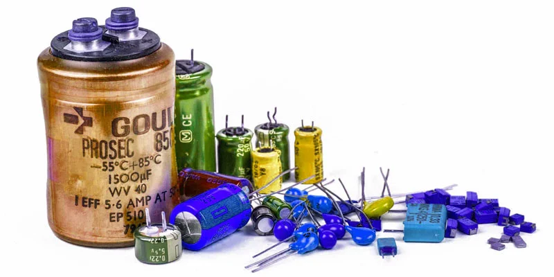
Capacitors are essential passive electronic components utilized for storing and releasing electrical energy through an electric field. Available in various sizes and shapes, they comprise two plates of conducting material, typically thin metal, separated by an insulator such as ceramic, film, glass, or even air. These versatile devices find application in creating oscillators, introducing time delays, providing power boosts, and serving numerous other functions in electronic circuits
Capacitor Markings Explained
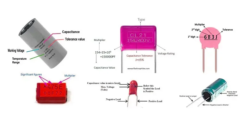
Deciphering capacitor markings is crucial for understanding their specifications. These markings typically include alphanumeric codes that denote capacitance, voltage rating, tolerance, and sometimes manufacturer details. For instance, a capacitor labeled “104K” indicates a capacitance of 100,000 picofarads (pF) with a tolerance of ±10%.
Capacitance Values: how to Read Capacitor Value
Capacitance, measured in farads (F), represents a capacitor’s ability to store charge per unit voltage. However, most capacitors feature smaller capacitance values, often expressed in microfarads (µF) or picofarads (pF). Understanding capacitance values is essential for selecting the right capacitor for your circuit, ensuring optimal performance.
How to Read Capacitor Value?
A step-by-step guide to interpreting readings
Step 1: Know the Units of Measurement
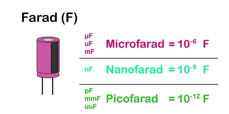
Capacitance is measured in farads (F). Common units include microfarads (µF), nanofarads (nF), and picofarads (pF).
1 µF, uF, or mF = 1 microfarad = 10-6 farads. (Careful — in other contexts, mF is the official abbreviation for millifarads or 10-3 farads.)
1 nF = 1 nanofarad = 10-9 farads.
1 pF, mmF, or uuF = 1 picofarad = 1 micromicrofarad = 10-12 farads.
Step 2: Read the Capacitance Value
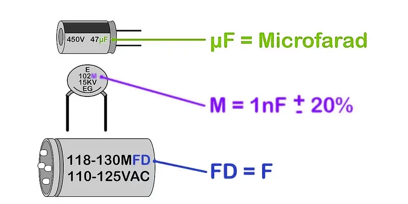
Most large capacitors have the capacitance value written directly on them. Adjust for variations in units.
Ignore capital letters in the units. For example, “MF” is just a variation of “mf.” (It is definitely not a megafarad, even though this is the official SI abbreviation.)
Don’t get thrown by “fd.” This is just another abbreviation for farad. For example, “mmfd” is the same as “mmf.”
Beware of single-letter markings such as “475m,” usually found on smaller capacitors. The meaning remains unchanged.
Step 3: Look for a Tolerance Value
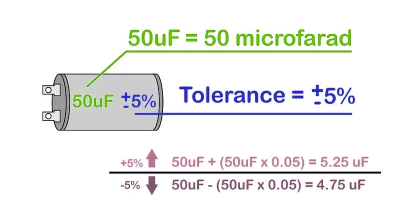
Tolerance indicates how much the actual capacitance can vary. This may be shown as a percentage or a letter code.
This isn’t crucial in all circuits, but you might need to pay attention to this if you require a precise capacitor value. For instance, a capacitor labeled “6000uF +50%/-70%” could actually have a capacitance as high as 9000uF (6000uF + 3000uF) or as low as 1800uF (6000uF – 4200uF).
If there is no percentage listed, look for a single letter after the capacitance value or on its own line. This letter may indicate a tolerance value, described below.
Step 4: Check the Voltage Rating
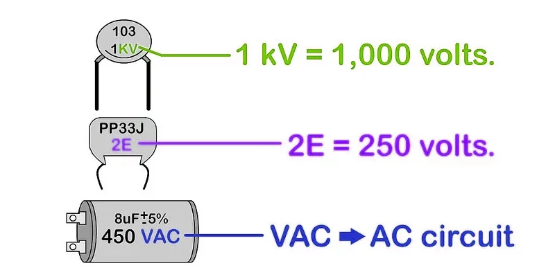
The voltage rating, often listed with a ‘V’, indicates the maximum voltage the capacitor can handle.
1 kV = 1,000 volts.
If you suspect your capacitor uses a code for voltage (a single letter or one digit and one letter), see below for details. If there is no symbol at all, reserve the capacitor for low-voltage circuits only.
For AC circuits, use a capacitor rated specifically for VAC. Do not use a DC capacitor unless you thoroughly understand how to convert the voltage rating and safely use it in AC applications.
Step 5: Look for a + or – Sign
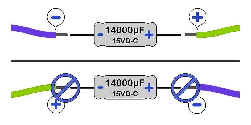
Polarized capacitors have a + or – sign to show polarity. Connect the + end to the positive side of the circuit.
Some capacitors use a colored bar or a ring-shaped depression to indicate polarity. On aluminum electrolytic capacitors, usually shaped like tin cans, this mark designates the negative (-) end. On small tantalum electrolytic capacitors, this mark designates the positive (+) end. Disregard the bar if it contradicts a + or – sign, or if it is on a non-electrolytic capacitor.
Step 6: Understand Temperature Coefficient (if applicable)
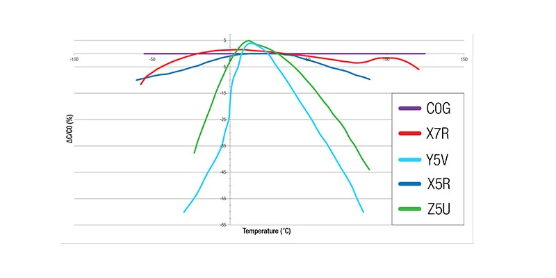
Capacitors often feature temperature coefficient markings such as NP0, X7R, or Y5V. These codes represent the capacitor’s stability across temperature ranges:
NP0 (C0G): NP0 capacitors are ideal for precision applications where temperature variations must be minimized.
X7R: Capacitors with an X7R temperature coefficient have a moderate capacitance change over temperature, typically within ±15%.
Y5V: Y5V capacitors have a high-temperature coefficient, resulting in significant capacitance variations with temperature fluctuations, often exceeding ±30%.
Step 8: Identify Date Codes and Lifespan
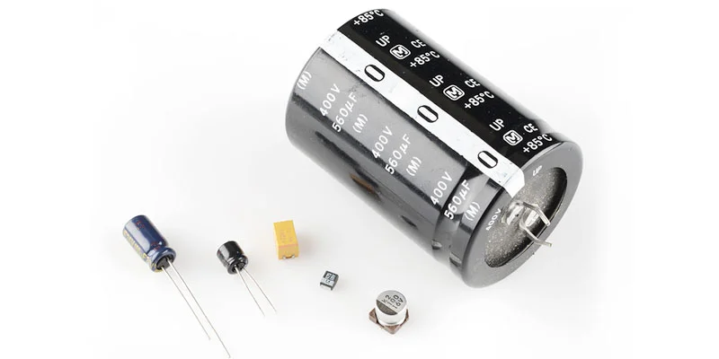
Large capacitors might include date codes indicating their manufacture date.
Knowing this can help determine their expected lifespan and reliability in your application.
How to Read Capacitor With Multimeter?
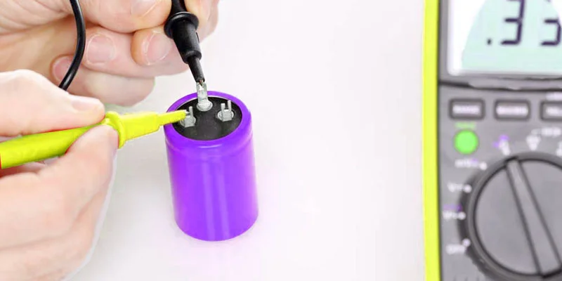
Power Off:
Always ensure that the power to the circuit is turned off before making any measurements. This prevents accidents and ensures safety.
Select Measurement Mode:
Determine the type of measurement you need to take. Common measurement modes include voltage, current, resistance, capacitance, and continuity. Select the appropriate mode on your multimeter dial.
Set Range:
Choose the appropriate range for your measurement. Start with the highest range and work your way down until you get a reading that falls within the display range of your multimeter.
Connect Leads:
Connect the test leads to the appropriate sockets on the multimeter. For voltage, resistance, and continuity measurements, use the red lead in the VΩmA socket and the black lead in the COM socket. For current measurements, move the red lead to the 10A socket.
Connect to Circuit:
Connect the test leads to the circuit you’re measuring. Ensure proper polarity and secure connections to avoid inaccurate readings.
Read Display:
Take note of the reading displayed on the multimeter. For voltage, resistance, and continuity measurements, the displayed value indicates the magnitude of the parameter being measured. For current measurements, ensure the value is within the range supported by your multimeter to avoid damage.
Interpret Reading:
Interpret the reading based on your measurement requirements and the expected values for the component or circuit you’re testing. Compare the reading to known standards or reference values to assess the health and functionality of the component or circuit.
Troubleshooting:
If the reading deviates significantly from expected values or indicates a fault, troubleshoot the circuit or component further. Check for loose connections, damaged components, or other issues that may affect the measurement.
Document Results:
Record the measurement results, along with any observations or notes, for future reference. Documenting measurements can aid in diagnosing problems, tracking changes over time, and maintaining records for regulatory compliance or documentation purposes.
Safety Precautions:
After completing measurements, disconnect the test leads from the circuit and switch off the multimeter. Store the multimeter and test leads in a safe location, away from moisture, heat, or other hazards.
Kind Tips
capacitor reading higher than the rating
If you find that a capacitor reading is higher than its rating, check the connections, remeasure, and consider replacing the capacitor if necessary.
capacitor reading lower than the rating
If a capacitor reading is lower than its rating, check connections, verify measurements, and consider replacement if necessary.
Types of Capacitors
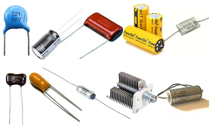
Ceramic Capacitors
Ceramic capacitors are among the most common types, prized for their small size, reliability, and low cost. These capacitors utilize a ceramic material as the dielectric, offering excellent stability and temperature performance.
How to Read Ceramic Capacitor Value
Ceramic capacitors typically have a three-digit code printed on them. The first two digits represent the significant figures, and the third digit is a multiplier. For example, if you see “104” printed on a ceramic capacitor, it means 10 + 4 zeros, so the capacitance is 100,000 picofarads (pF), which is the same as 0.1 microfarads (μF).
Electrolytic Capacitors
Electrolytic capacitors are renowned for their high capacitance values, making them ideal for applications requiring large capacitance in a compact form factor. They utilize an electrolyte as the dielectric and are available in both aluminum and tantalum variants.
How to Read Electrolytic Capacitor
Electrolytic capacitors have their capacitance value and voltage rating printed on them. For example, “47μF 25V” means the capacitance is 47 microfarads and the voltage rating is 25 volts.
Tantalum Capacitors
Tantalum capacitors, a subtype of electrolytic capacitors, exhibit superior performance in terms of capacitance density and voltage rating. Their exceptional stability and reliability make them indispensable in critical applications where precision is paramount.
How to Read Tantalum Capacitor
Tantalum capacitors have their capacitance value and voltage rating printed on them. For example, “10μF 25V” means the capacitance is 10 microfarads and the voltage rating is 25 volts.
Film Capacitors
Film capacitors employ a thin plastic film as the dielectric, offering excellent self-healing properties and high insulation resistance. They are prized for their reliability, longevity, and high operating temperatures.
How to Read Film Capacitor Values
Film capacitors have their capacitance value directly printed on them in picofarads (pF), nanofarads (nF), or microfarads (μF). For example, “473” means 47,000 pF or 47 nF, and “0.1μ” means 0.1 μF.
Supercapacitors
Supercapacitors, also known as ultracapacitors, are a special type of capacitor designed to store and release large amounts of energy rapidly. They find applications in energy storage systems, hybrid vehicles, and regenerative braking systems.
Variable Capacitors
Variable capacitors, as the name suggests, possess adjustable capacitance values, making them ideal for tuning radio frequency (RF) circuits and variable-frequency oscillators. Their capacitance can be varied by mechanically altering the distance between the plates or by employing a variable dielectric material.
Mica Capacitors
Mica capacitors utilize mica as the dielectric, offering exceptional stability, high precision, and low dielectric losses. They are commonly used in high-frequency applications, where accuracy and reliability are paramount.
Polystyrene Capacitors
Polystyrene capacitors, known for their low dielectric absorption and excellent temperature stability, are suitable for precision applications requiring minimal distortion and drift. They find applications in audio circuits, precision timing circuits, and instrumentation.
Glass Capacitors
Glass capacitors employ glass as the dielectric, offering high stability, low losses, and excellent insulation resistance. They are used in high-voltage applications, pulse circuits, and medical devices.
Solid Tantalum Capacitors
Solid tantalum capacitors are a subtype of tantalum capacitors known for their robust construction, high reliability, and extended lifespan. They are commonly utilized in aerospace, military, and medical applications, where durability and performance are critical.
FAQs
Are all capacitors polarized?
No, not all capacitors are polarized. While electrolytic capacitors and tantalum capacitors are polarized and must be connected with the correct polarity, ceramic capacitors and film capacitors are non-polarized and can be connected in any orientation.
What factors should I consider when selecting a capacitor for my application?
When selecting a capacitor, consider parameters such as capacitance value, voltage rating, temperature stability, tolerance, and ESR (Equivalent Series Resistance). Additionally, factors like size, cost, and environmental conditions should be taken into account to ensure optimal performance and reliability.
Can I use a capacitor with a higher voltage rating than required for my application?
It is generally acceptable to use a capacitor with a higher voltage rating than required for your application. However, using a capacitor with a significantly higher voltage rating may result in increased size, cost, and parasitic effects. It’s essential to strike a balance between voltage rating and other performance parameters to meet the application requirements effectively.
What are the common failure modes of capacitors?
Common failure modes of capacitors include capacitance loss, leakage current increase, dielectric breakdown, and mechanical damage. These failures can occur due to overvoltage conditions, prolonged exposure to high temperatures, mechanical stress, or manufacturing defects.
How can I test a capacitor to determine if it’s faulty?
Capacitors can be tested using a multimeter set to the capacitance measurement mode. Disconnect the capacitor from the circuit, discharge it, and then connect the multimeter leads to the capacitor terminals. The multimeter will display the capacitance value, allowing you to determine if the capacitor is within its specified range. Additionally, visual inspection for physical damage or bulging can indicate capacitor failure.
Conclusion
Mastering the art of How to Read Capacitor opens doors to limitless possibilities in electronics. By understanding capacitor markings and values, you can confidently select the right components for your projects, ensuring optimal performance and reliability.