In the ever-evolving world of electronics, understanding and accurately identifying integrated circuit chips is a crucial skill. How to Identify Integrated Circuit Chip is a question that often perplexes both novice enthusiasts and seasoned professionals.
In this comprehensive guide to Integrated Circuit Identification, we aim to demystify the process and equip you with the knowledge and tools needed to confidently recognize these tiny yet powerful components.
What is Integrated Circuits?

An integrated circuit, often abbreviated as IC, is a miniature electronic circuit consisting of transistors, resistors, capacitors, and other components that are fabricated on a single semiconductor substrate, usually a silicon wafer.
These circuits play a vital role in modern electronics as they enable the miniaturization and increased functionality of electronic devices. For example, the microprocessors that power our computers and smartphones are highly complex integrated circuits. Integrated circuits can be divided into different types based on their functions and applications. Digital integrated circuits process digital signals and perform logical operations, while analog integrated circuits process continuous signals (such as those in audio systems).
They have revolutionized the electronics industry by enabling smaller, more efficient, and more powerful devices. Before the advent of integrated circuits, electronic circuits were built using discrete components, which were larger, less reliable, and more difficult to assemble.
What Are the Tools to Identify Ics by Marking?
The tools used for identifying Integrated Circuits (ICs) based on their markings include:
Step 1: Magnifying Tools
1.1 Magnifying Glass
– A simple magnifying glass can help enlarge the markings on the IC surface, making them easier to read. It’s handy for chips with moderately sized markings.
– For example, when dealing with ICs in through-hole packages like DIP, a handheld magnifying glass can provide sufficient magnification.
1.2 Digital Microscope
– A digital microscope offers higher magnification and the ability to capture images of the markings. This is especially useful for very small or finely detailed markings.
– If the IC has surface-mount technology (SMT) with tiny markings, a digital microscope can clearly show the characters and symbols.
Step 2: Lighting Equipment
2.1 Directional Light Source
– A focused light, such as a desk lamp with a directional shade, can be aimed at the IC to minimize shadows and enhance the visibility of the markings.
– This is helpful when the IC has uneven or reflective surfaces.
2.2 LED Ring Light
– Attaching an LED ring light around the microscope or magnifying glass can provide uniform and bright illumination, ensuring clear viewing of the markings.
Step 3: Marking Documentation and Databases
3.1 Electronic Component Catalogs
– These printed or digital catalogs contain information about various ICs and their typical markings. They can serve as a reference for comparison.
– For instance, popular component manufacturers often publish catalogs that list their products and associated markings.
3.2 Online Component Databases
– Websites and platforms dedicated to electronic components have extensive databases where you can search for ICs based on their markings.
– Examples include component identification websites and forums where users share their identification experiences.
Step 4: Cleaning Supplies
4.1 Soft Brush
– To gently remove dirt or debris from the IC surface that might obscure the markings.
– A soft-bristled brush can be used without causing damage to the chip.
4.2 Isopropyl Alcohol and Clean Cloth
– To clean stubborn dirt or residue on the IC, a small amount of isopropyl alcohol on a clean cloth can be used.
Having the right combination of these tools and resources can significantly improve the accuracy and efficiency of identifying ICs based on their markings.
How to Identify Integrated Circuit Chip?
How to identify integrated circuit chip? Guide to Integrated Circuit IdentificationIdentifying an integrated circuit (IC) chip requires a systematic approach and a certain level of technical knowledge. Here is a detailed guide:
Step 1: Physical Inspection
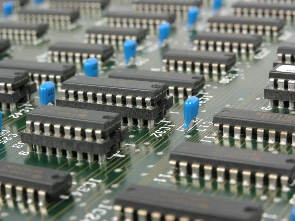
1.1 Observe the Packaging
– Take note of the shape and size of the package. Common types include DIP (Dual In-line Package), SOP (Small Outline Package), QFN (Quad Flat No-lead), and BGA (Ball Grid Array). Different packages are often associated with specific functions or applications.
– For example, older and simpler ICs might be in DIP packages, while modern high-density chips are more likely to be in BGA or QFN.
1.2 Check the Markings
– Look carefully for any markings on the chip’s surface. These can include the manufacturer’s logo, part number, batch code, and date code.
– Sometimes, there might be additional markings indicating special features or revisions of the chip.
1.3 Inspect the Pin Configuration
– Count the number of pins and note their arrangement. The pin configuration can provide clues about the chip’s functionality.
– For instance, chips with a large number of pins are likely to have more complex functions.
Step 2: Data Sheet Research
2.1 Use Markings to Search
– Enter the part number or other relevant markings from the chip into search engines or specialized electronic component databases.
– Popular component search websites and manufacturer websites can be valuable resources.
2.2 Analyze the Data Sheet
– Once you find the data sheet, carefully study its contents. It will provide detailed information about the chip’s functionality, electrical characteristics (such as voltage and current ratings), pinout diagram, and application examples.
Step 3: Electrical Testing
3.1 Multimeter Measurements
– Use a multimeter to measure the resistance, capacitance, and voltage across different pins of the chip. Compare these measurements with the values specified in the data sheet.
– For example, if it’s a voltage regulator chip, measure the output voltage to ensure it’s within the expected range.
3.2 Oscilloscope and Logic Analyzer Usage
– For more complex signals or digital circuits, an oscilloscope or logic analyzer can be employed to monitor and analyze the waveforms and logic states on the pins.
Step 4: Functional Testing
4.1 Build a Test Circuit
– Based on the expected functionality of the chip, design and construct a simple test circuit.
– For a transistor amplifier IC, set up an input signal and measure the amplified output.
4.2 Observe and Verify Operation
– Power up the test circuit and observe if the chip functions as described in the data sheet and expected behavior.
Step 5: Component Databases and Forums
5.1 Refer to Online Databases
– Explore comprehensive component databases that contain information on a wide range of ICs.
– Some databases also have user-contributed identification experiences and tips.
5.2 Engage in Electronics Forums
– Participate in electronics forums where experts and enthusiasts share their knowledge and experiences. You can post pictures and details of the chip for assistance.
Step 6: Reverse Engineering (In Special Cases)
6.1 Decap and Microscopy (Advanced Technique)
– In rare cases, if all other methods fail and it’s necessary, the chip can be decapsulated and inspected under a microscope to analyze the internal circuitry. This is a highly specialized and destructive method.
Identifying an IC chip might not always be straightforward and may require patience and a combination of these methods. It’s also crucial to handle the chip with care to avoid damage during the identification process.
Common Misunderstandings

In the process of identifying integrated circuit chips, there are some common misunderstandings and precautions that need to be noted:
- Relying solely on appearance similarity: Sometimes different models of chips may have similar appearances. Judging only based on appearance can easily lead to incorrect identification.
- Misinterpreting manufacturer logos: Manufacturer logos may change or there may be similar logos, causing confusion.
- Ignoring version and revision numbers: Chips may have different versions and revision numbers. These subtle differences may vary in function and performance. Ignoring them may lead to incorrect applications.
Conclusion
Identifying integrated circuit chips is a task that demands attention to detail, technical knowledge, and caution. The process involves a series of steps and considerations to accurately determine the type and functionality of the chip.
Avoiding the common misunderstandings such as relying too heavily on appearance or misinterpreting manufacturer details is crucial. Adhering to the precautions like electrostatic protection, proper storage and transportation, and correct tool usage helps prevent damage to the chips and ensures the reliability of the identification process.
With a systematic approach and awareness of the potential pitfalls, one can enhance the accuracy and efficiency of integrated circuit chip identification, which is essential in various fields of electronics and technology.