Capacitors are essential components in electronic circuits, storing and releasing electrical energy. When it comes to optimizing circuit performance, combining non nonpolar capacitors effectively can make a significant difference.
This article delves into the intricacies of combining these capacitors to maximize efficiency and performance.
What is a Non-Polarized Capacitor?
A non-polarized capacitor, also known as a bipolar capacitor, is a type of capacitor that can be connected in any orientation within an electronic circuit.
Unlike polarized capacitors, which have specific positive and negative terminals, non-polarized capacitors do not have polarity restrictions. This means they can be inserted into a circuit without concern for the orientation of their leads. Non-polarized capacitors are commonly used in various applications, including filtering, coupling, and timing circuits, where their versatility and ease of use make them advantageous.
How Do Non-Polarized Capacitors Work
Non-polarized capacitors, also referred to as bipolar capacitors, function similarly to other types of capacitors but with the advantage of not having polarity restrictions. Here’s how they work:
Capacitor Structure: Like all capacitors, non-polarized capacitors consist of two conductive plates separated by an insulating material called a dielectric. These plates can be made of various materials, such as metal foil or conductive polymer, while the dielectric material can be ceramic, polyester, or other materials.
Charge Storage: When a voltage is applied across the terminals of a non-polarized capacitor, electrons accumulate on one plate, creating a negative charge, while the other plate becomes positively charged. This charge separation results in an electric field between the plates.
Energy Storage: The electric field between the plates stores energy in the form of an electrostatic field. This stored energy can be released when needed, making capacitors useful for tasks like filtering noise, smoothing voltage fluctuations, and timing circuits.
No Polarity Restrictions: Unlike polarized capacitors, which have specific positive and negative terminals, non-polarized capacitors can be connected in any orientation within a circuit. This versatility simplifies circuit design and installation, as there’s no need to worry about connecting them the wrong way.
Applications: Non-polarized capacitors find applications in various electronic circuits, including audio systems, power supplies, amplifiers, and signal processing circuits. Their ability to work in any orientation makes them suitable for both AC (alternating current) and DC (direct current) circuits.
Types of Non Nonpolar Capacitors

Non nonpolar capacitors, also known as bipolar capacitors, encompass various capacitor types, each with its characteristics and suitability for different applications.
Here are some common types of non nonpolar capacitors:
Ceramic Capacitors:
Description: Ceramic capacitors use a ceramic material as the dielectric, sandwiched between two conductive plates.
Characteristics: They offer high stability, low losses, and wide capacitance ranges. Ceramic capacitors are suitable for high-frequency applications and decoupling circuits.
Applications: Used in timing circuits, noise suppression, RF coupling, and general-purpose filtering.
Film Capacitors:
Description: Film capacitors use a thin polymer film as the dielectric, providing excellent electrical insulation and stability.
Characteristics: They offer high reliability, low dielectric absorption, and good self-healing properties. Film capacitors are available in various types, including polyester, polypropylene, and polycarbonate.
Applications: Widely used in audio applications, power factor correction, motor run capacitors, and high-voltage applications.
Tantalum Capacitors:
Description: Tantalum capacitors use tantalum metal as the anode material and a conductive polymer or manganese dioxide as the cathode material.
Characteristics: They offer high capacitance density, low leakage current, and stable performance over a wide temperature range. Tantalum capacitors are polarized and must be connected with the correct polarity to prevent damage.
Applications: Commonly used in portable electronics, telecommunications equipment, and power supply filtering due to their small size and high capacitance values.
Polymer Capacitors:
Description: Polymer capacitors use conductive polymers as the electrolyte material, offering improved performance and reliability compared to traditional electrolytic capacitors.
Characteristics: They provide low equivalent series resistance (ESR), high ripple current handling capabilities, and long operational life.
Applications: Used in high-current, high-frequency circuits, such as voltage regulator modules (VRMs), motherboards, and graphics cards in computer systems.
Mica Capacitors:
Description: Mica capacitors use natural or synthetic mica as the dielectric material, offering high stability and low dielectric losses.
Characteristics: They provide excellent temperature stability, high precision, and low capacitance tolerance. Mica capacitors are suitable for high-frequency and high-voltage applications.
Applications: Commonly used in RF circuits, oscillators, filters, and precision instrumentation.
These types of non nonpolar capacitors offer a wide range of options for various electronic applications, each with its advantages and suitability for specific circuit requirements.
How to Test Non-Polarized Capacitors
Testing non-polarized capacitors is essential to ensure their proper functionality within electronic circuits. Here’s a step-by-step guide on how to test them:
- Visual Inspection: Start by visually inspecting the capacitor for any signs of physical damage, such as cracks, bulges, or leaking electrolyte. If the capacitor appears damaged, it may need replacement.
- Discharge the Capacitor: Before testing, discharge the capacitor to ensure there’s no residual charge. Use a resistor or a discharge tool to safely discharge any stored energy.
- Use a Multimeter: Set your multimeter to the capacitance measurement mode. Connect the probes to the capacitor terminals, ensuring proper polarity if applicable. For non-polarized capacitors, polarity doesn’t matter.
- Measure Capacitance: Place the multimeter probes across the capacitor terminals and observe the reading on the capacitance scale. The measured capacitance should be within the specified tolerance range of the capacitor. If the reading deviates significantly from the rated capacitance, the capacitor may be faulty.
- Check for Short Circuits: Switch the multimeter to the resistance or continuity mode. Place the probes across the capacitor terminals. A short circuit or very low resistance reading indicates a faulty capacitor.
- Perform a Leakage Test: Set your multimeter to the resistance mode. Connect one probe to a capacitor terminal and the other probe to the opposite terminal while observing the resistance reading. A high resistance reading indicates low leakage, while a low resistance reading suggests leakage, indicating a faulty capacitor.
- Test with an ESR Meter: If available, use an equivalent series resistance (ESR) meter to measure the internal resistance of the capacitor. A higher than normal ESR reading may indicate a faulty capacitor.
- Compare with Manufacturer Specifications: Refer to the manufacturer’s specifications for the capacitor’s rated capacitance, voltage rating, and other parameters. Compare the measured values with these specifications to determine if the capacitor is functioning correctly.
- Repeat if Necessary: If the initial tests yield inconclusive results or if there are doubts about the capacitor’s condition, repeat the testing process or consider using alternative testing methods to confirm its functionality.
By following these steps, you can effectively test non-polarized capacitors to ensure their reliability and performance in electronic circuits.
Materials Required for Combination Non-Polarized Capacitors
Combining non-polarized capacitors requires a few basic materials to ensure proper connections and reliable performance within electronic circuits. Here’s a list of materials required for combining non-polarized capacitors:
- Non-Polarized Capacitors: The primary component needed for combining non-polarized capacitors is the capacitors themselves. Ensure that the capacitors have similar specifications, including capacitance values, voltage ratings, and temperature stability, to achieve balanced performance.
- Soldering Iron and Solder: A soldering iron and solder are necessary for soldering connections between the capacitor terminals and other components within the circuit. Proper soldering ensures secure and reliable electrical connections.
- Desoldering Pump or Wick (Optional): In case of incorrect connections or modifications, a desoldering pump or wick may be required to remove excess solder from connections.
- Wire Strippers: Wire strippers are essential for stripping insulation from wire ends, facilitating the soldering process and ensuring good electrical contact between components.
- Wire: Thin gauge wire is needed to make connections between capacitors, as well as between capacitors and other components within the circuit. Ensure that the wire is insulated and suitable for the voltage and current requirements of the circuit.
- Circuit Board or Breadboard: A circuit board or breadboard provides a platform for assembling and connecting the components of the circuit. Choose a board size and layout that accommodate the number of capacitors and other components required for the circuit.
- Multimeter: A multimeter is a handy tool for measuring capacitance, voltage, and continuity within the circuit. It helps verify proper connections and diagnose any potential issues during the combination process.
- Safety Equipment: Safety equipment such as safety glasses and heat-resistant gloves are essential for protecting against potential hazards associated with soldering and working with electronic components.
Factors to Consider Before Combining Capacitors
Before combining non nonpolar capacitors, several factors must be considered to ensure optimal performance:
- Capacitance Values: Matching capacitance values is crucial to ensure balanced voltage distribution and consistent performance.
- Voltage Ratings: Capacitors should have similar voltage ratings to prevent potential overloading or voltage breakdown.
- Temperature Stability: Consider the operating temperature range to ensure capacitors can withstand environmental conditions.
How to Combine Non Nonpolar Capacitors
Combining non nonpolar capacitors involves connecting them in different configurations to achieve desired capacitance values and performance characteristics.
Here’s a guide on how to combine non nonpolar capacitors effectively:
Understand Capacitor Configuration:
Before combining capacitors, it’s essential to understand the different configuration options available. The two primary configurations are parallel and series.
Parallel Configuration:
Connect Capacitors in parallel configuration, the positive terminals of all capacitors are connected, and the negative terminals are connected.
Increased Total Capacitance: When capacitors are connected in parallel, the total capacitance is the sum of the individual capacitance values. This configuration increases the overall capacitance while maintaining the voltage rating of each capacitor.
Formula for Total Capacitance: The formula for calculating the total capacitance in a parallel configuration is: Total Capacitance = C1 + C2 + C3 + … (where C1, C2, C3, etc., are the capacitance values of individual capacitors)
Series Configuration:
Connect Capacitors in Series: In a series configuration, the positive terminal of one capacitor is connected to the negative terminal of the next capacitor, forming a chain.
Increased Total Voltage Rating: When capacitors are connected in series, the total voltage rating is the sum of the voltage ratings of individual capacitors. This configuration increases the overall voltage handling capability while maintaining the total capacitance.
Formula for Total Voltage Rating: The formula for calculating the total voltage rating in a series configuration is: Total Voltage Rating = V1 + V2 + V3 + … (where V1, V2, V3, etc., are the voltage ratings of individual capacitors)
Mixed Configuration:
For specific applications, a combination of parallel and series configurations may be necessary to achieve desired capacitance and voltage ratings.
By combining both configurations strategically, you can tailor the circuit to meet specific performance requirements.
Verify Connections
After connecting the capacitors in the desired configuration, verify the connections to ensure they are secure and free from solder bridges or other faults.
Testing
Once the capacitors are combined, use a multimeter or other testing equipment to verify the capacitance and voltage ratings of the combined capacitors. Ensure that the measured values align with the desired specifications for the circuit.
By following these steps, you can effectively combine non nonpolar capacitors to optimize circuit performance and achieve desired capacitance and voltage characteristics for various electronic applications.
Difference Between Polarized and Nonpolarized Capacitor
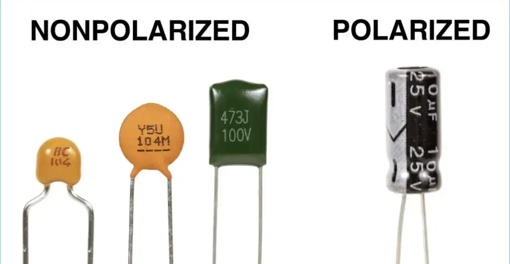
The primary difference between polarized and nonpolarized capacitors lies in their construction and electrical properties:
Construction:
Polarized Capacitors: Polarized capacitors have distinct positive and negative terminals and are designed to be connected in a specific polarity within a circuit. Common types of polarized capacitors include electrolytic capacitors, such as aluminum electrolytic and tantalum capacitors.
Nonpolarized Capacitors: Nonpolarized capacitors, also known as bipolar capacitors, do not have polarity restrictions and can be connected in any orientation within a circuit. They typically consist of two conductive plates separated by a dielectric material and are commonly made from ceramic, film, or other materials.
Electrical Properties:
Polarization: Polarized capacitors have a dielectric material that is sensitive to voltage polarity. Connecting polarized capacitors in reverse polarity can lead to voltage breakdown, permanent damage, or even explosion in extreme cases.
Orientation Flexibility: Nonpolarized capacitors do not exhibit polarity sensitivity and can be connected in any orientation within a circuit without the risk of damage due to reverse polarity. This flexibility simplifies circuit design and installation.
Applications:
Polarized Capacitors: Polarized capacitors are commonly used in applications where high capacitance values and voltage ratings are required, such as power supply filtering, audio amplification, and signal coupling.
Nonpolarized Capacitors: Nonpolarized capacitors find applications in circuits where polarity flexibility is essential or where AC signals are present. They are often used in timing circuits, audio crossover networks, and coupling circuits.
Capacitance Values:
Polarized Capacitors: Polarized capacitors typically have higher capacitance values compared to nonpolarized capacitors. This allows them to store more charges and handle higher current requirements.
Nonpolarized Capacitors: Nonpolarized capacitors usually have lower capacitance values compared to polarized capacitors but offer the advantage of versatility in circuit orientation.
Here’s a comparison table highlighting the difference between polar and nonpolar capacitors:
| Feature | Polarized Capacitors | Nonpolarized Capacitors |
|---|---|---|
| Construction | Have distinct positive and negative terminals. | Do not have polarity restrictions; can be connected in any orientation. |
| Types | Electrolytic (e.g., aluminum electrolytic, tantalum) | Ceramic, film, etc. |
| Polarity Sensitivity | Sensitive to voltage polarity; must be connected in correct orientation to prevent damage. | No polarity sensitivity; can be connected in any orientation without risk of damage. |
| Voltage Ratings | Typically have higher voltage ratings. | Voltage ratings vary depending on capacitor type; generally lower than polarized capacitors. |
| Capacitance Values | Typically have higher capacitance values. | Generally have lower capacitance values compared to polarized capacitors. |
| Applications | Commonly used in applications requiring high capacitance values and voltage ratings, such as power supply filtering and audio amplification. | Used in circuits where polarity flexibility is essential or where AC signals are present, such as timing circuits and audio crossover networks. |
| Flexibility | Limited flexibility due to polarity restrictions. | Offers flexibility in circuit orientation, simplifying circuit design and installation. |
Tips for Optimal Capacitor Combination
To optimize capacitor combination and ensure reliable circuit performance, consider the following tips:
- Matching Capacitor Parameters: Select capacitors with similar parameters, including capacitance, voltage rating, and temperature stability.
- Balanced Current Sharing: Ensure even current distribution among parallel-connected capacitors to prevent unequal voltage drops.
- Thermal Management: Monitor and manage capacitor temperatures to prevent overheating and degradation.
FAQs
Can I combine capacitors with different capacitance values?
Yes, but it’s essential to calculate the equivalent capacitance accurately to avoid imbalances in the circuit.
What happens if I exceed the voltage rating of capacitors?
Exceeding the voltage rating can lead to capacitor breakdown, resulting in permanent damage or failure.
Can I mix different types of capacitors in one circuit?
While possible, mixing capacitor types should be done cautiously, considering compatibility and performance requirements.
How do I determine the optimal configuration for my circuit?
Consider the specific requirements of your circuit, including voltage, current, and frequency, to determine the most suitable capacitor configuration.
What is the significance of temperature stability in capacitors?
Temperature stability ensures consistent performance across varying environmental conditions, preventing drift or deviation in capacitance values.
How can I test the combined capacitors for performance?
Utilize appropriate testing equipment, such as capacitance meters and oscilloscopes, to evaluate the performance of combined capacitors accurately.
Conclusion
Combining non nonpolar capacitors offers a versatile approach to enhance circuit performance and efficiency. By understanding the principles of capacitor combination and following best practices, you can optimize your circuits for various applications. Remember to select capacitors carefully, consider configuration options, and monitor performance to achieve optimal results.
Looking to optimize your electronic circuits with non nonpolar capacitors? Whether you’re designing a high-frequency RF circuit or a low-power audio amplifier, choosing the right capacitor type is crucial for achieving optimal performance. Explore our selection of non nonpolar capacitors and take your circuits to the next level!
Shop Now for Non Nonpolar Capacitors and Unlock Peak Performance!