Crystal oscillators are the heartbeat of many electronic devices, providing the precise timing needed for proper operation. However, troubleshooting these tiny components can be tricky. This blog post aims to demystify the process, offering practical methods to check if your crystal oscillator is functioning correctly.
We’ll explore techniques using common tools like multimeters and oscilloscopes, outlining step-by-step procedures. Whether you’re a seasoned engineer or a hobbyist, understanding how to diagnose crystal oscillator issues will save you time and frustration in your electronic projects.
What Are Crystal Oscillators
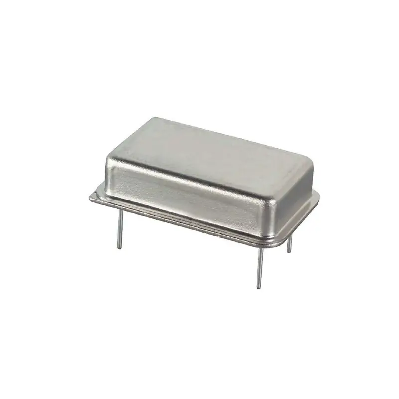
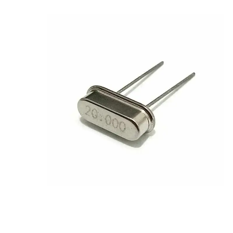
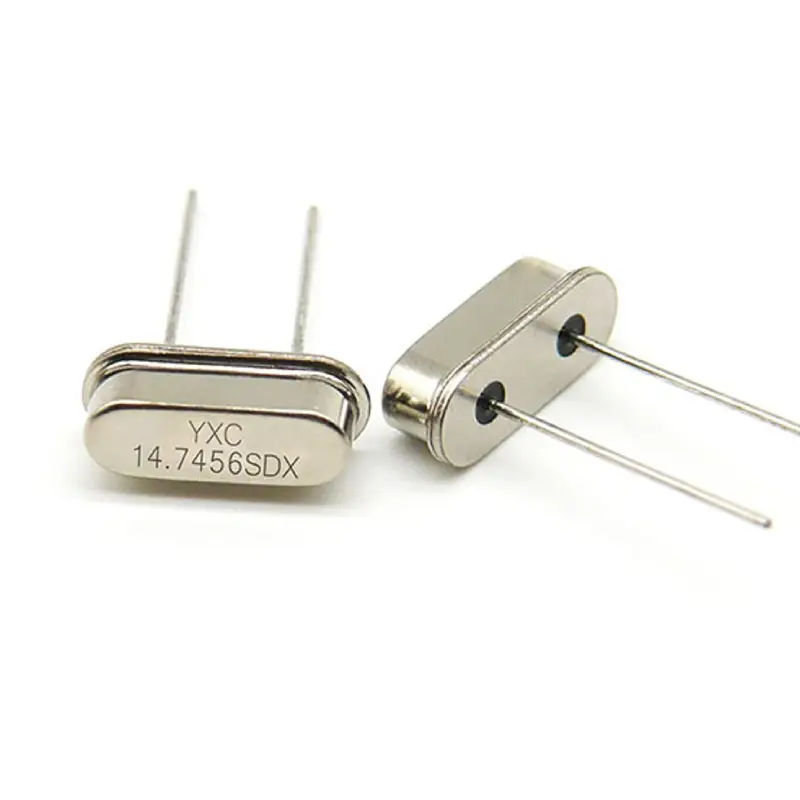
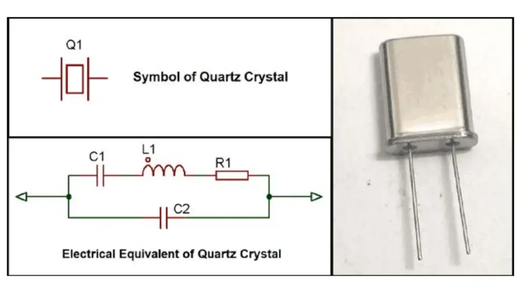
Crystal oscillators are electronic circuits that generate a precise and stable frequency signal. They rely on the piezoelectric effect of quartz crystals, which vibrate at a specific resonant frequency when subjected to an electrical field. This inherent stability makes them crucial for applications requiring accurate timing.
- Key Function: Provides a stable clock signal.
- Core Component: Quartz crystal.
- Operational Principle: Piezoelectric effect.
- Result: Precise frequency output.
These oscillators are fundamental in various electronic devices, from microcontrollers and computers to communication systems and consumer electronics. The consistent timing they provide ensures synchronized operations and reliable data processing. They are the timing backbone of many electronic systems.
How to Check Crystal Oscillator?
Crystal oscillators are crucial for timing in electronics. Verifying their functionality ensures accurate circuit operation. This guide provides a step-by-step process for checking crystal oscillators using basic tools.
Step 1: Visual Inspection and Power Check
First and foremost, before any electrical testing, conduct a thorough visual inspection of the crystal oscillator and its surrounding circuitry. Look for any signs of physical damage, such as cracks, burns, or loose connections. Ensure the crystal itself is securely mounted on the PCB and that there are no visible signs of corrosion or oxidation. A damaged crystal or faulty connection can prevent the oscillator from functioning correctly.
Next, verify that the circuit is receiving the correct power supply. Use a multimeter set to DC voltage mode to check the voltage across the power pins of the crystal oscillator circuit. Compare the measured voltage to the specifications listed in the oscillator’s datasheet. Incorrect voltage levels can lead to erratic behavior or complete failure of the oscillator. Also, check for any nearby components that may be overheating.
- Visual Inspection: Look for physical damage.
- Power Check: Verify correct voltage levels.
- Component Temperature: Check for overheating.
Step 2: Continuity and Resistance Checks
Before powering up the circuit, perform continuity and resistance checks to identify potential short circuits or open connections. Use a multimeter in continuity mode to check the connections between the crystal oscillator pins and the surrounding components. Verify that there are no unintended short circuits between the power and ground pins. If continuity is not present where it should be, a break in the circuit is indicated.
Switch the multimeter to resistance mode and check the resistance between the crystal pins and the associated components. This will help identify any components that may have failed or are out of tolerance. Pay close attention to the resistors in the oscillator circuit, as their values are critical for proper operation. Compare the measured resistance values to the schematic or datasheet.
- Continuity Check: Verify proper connections.
- Resistance Check: Identify faulty components.
- Component Comparison: Compare to datasheets.
Step 3: Frequency and Signal Integrity Checks
For accurate frequency measurement, an oscilloscope or frequency counter is essential. Connect the oscilloscope probe to the output pin of the crystal oscillator. Observe the waveform and measure the frequency. Verify that the measured frequency matches the specifications listed in the oscillator’s datasheet. A stable and clean waveform indicates proper operation. If the waveform is distorted or the frequency is incorrect, the oscillator may be faulty.
Check the signal integrity of the output signal. Look for any signs of noise, jitter, or distortion. These issues can indicate problems with the oscillator circuit or surrounding components. Use the oscilloscope to measure the signal’s amplitude and rise/fall times. Compare these values to the specifications in the datasheet. If possible, compare the output waveform to a known good waveform.
- Frequency Measurement: Use an oscilloscope or frequency counter.
- Signal Integrity: Check for noise and distortion.
- Waveform Analysis: Compare to datasheet specifications.
How to Check Crystal Oscillator With Multimeter
Crystal oscillators are vital for precise timing in electronic circuits. While a multimeter has limitations, it can still provide valuable insights into their functionality. This guide outlines how to use a multimeter to check a crystal oscillator.
Step 1: Visual Inspection and Power Verification
Begin by visually inspecting the crystal oscillator and its surrounding circuit for any signs of physical damage, such as cracks, burns, or loose connections. Ensure the crystal is properly seated and that there are no visible signs of corrosion. A careful visual check can often reveal obvious faults before any electrical testing.
Next, verify that the circuit is receiving the correct power supply. Set your multimeter to DC voltage mode and measure the voltage across the crystal oscillator’s power pins. Compare the measured voltage to the specifications in the oscillator’s datasheet. Incorrect voltage levels can prevent the oscillator from functioning or even damage it.
Step 2: Continuity and Basic Resistance Checks
Before applying power, perform continuity checks to ensure there are no short circuits or open connections in the oscillator circuit. Use your multimeter’s continuity function to check the connections between the crystal pins and the surrounding components. Confirm that there are no unintended short circuits between the power and ground lines.
Then, switch your multimeter to resistance mode and measure the resistance between the crystal’s pins and the associated components. This can help identify any components that have failed or are out of tolerance. Pay particular attention to resistors in the oscillator circuit, as their values are critical. Compare your measurements to the values listed in the circuit’s schematic or the component datasheets.
Step 3: Checking for AC Voltage (Limited Capability)
With the circuit powered on, and with utmost caution, you can attempt to measure the AC voltage at the crystal oscillator’s output pin. However, this method has limitations. Most multimeters have a limited frequency response, and high-frequency crystal oscillators may not register accurately. A small AC voltage reading might indicate activity, but it’s not a definitive test of frequency.
If your multimeter has a frequency measurement function, and the oscillator’s frequency is within its range, you can try measuring the frequency directly. However, this is still limited by the multimeter’s accuracy and frequency range. For accurate frequency measurement, an oscilloscope or frequency counter is recommended. Remember, a multimeter is best used for basic checks, not precise frequency measurements of crystal oscillators.
How to Check Crystal Oscillator Using Oscilloscope
Crystal oscillators provide crucial timing signals. An oscilloscope offers a precise way to verify their functionality, allowing you to examine both frequency and signal integrity. Here’s a step-by-step guide.
Step 1: Power and Ground Verification
Before connecting the oscilloscope, ensure the crystal oscillator circuit is powered correctly. Use a multimeter to verify the DC voltage at the oscillator’s power pins, comparing it to the datasheet specifications. Also, confirm a stable ground connection. A faulty power supply or ground can lead to inaccurate oscilloscope readings.
Connect the oscilloscope’s ground clip to the circuit’s ground point, as close as possible to the oscillator. This minimizes ground loop effects, which can introduce noise and distortion into the measurement. Ensure the oscilloscope is powered on and properly calibrated.
Step 2: Frequency Measurement and Waveform Observation
Connect the oscilloscope probe to the crystal oscillator’s output pin. Set the oscilloscope’s time base and voltage scale to display a clear waveform. Adjust the trigger level to stabilize the waveform. Measure the frequency using the oscilloscope’s built-in measurement functions or by calculating it from the time period of the waveform.
Observe the waveform’s shape. A clean, stable sine wave or square wave (depending on the oscillator type) indicates proper operation. Look for any signs of distortion, noise, or jitter. These anomalies can indicate problems with the oscillator or its surrounding circuitry. Compare the measured frequency to the oscillator’s datasheet specifications.
Step 3: Signal Integrity and Stability Analysis
Use the oscilloscope to measure the signal’s amplitude, rise time, and fall time. Compare these values to the specifications provided in the crystal oscillator’s datasheet. Deviations from the expected values can indicate a faulty oscillator or issues with the supporting circuitry.
Observe the waveform over an extended period to assess its stability. Look for any frequency drift or variations in amplitude. A stable waveform indicates a reliable oscillator. Use the oscilloscope’s advanced features, such as FFT (Fast Fourier Transform), to analyze the signal’s frequency spectrum and identify any unwanted harmonics or noise components. This provides a more detailed view of the oscillator’s performance.
How to Check if Crystal Oscillator is Working
Crystal oscillators are essential for precise timing in electronic devices. To ensure proper operation, a combination of visual inspection and electrical testing is necessary. Here’s a comprehensive guide to checking if a crystal oscillator is working.
Step 1: Visual Inspection and Power Supply Check
Begin with a thorough visual inspection of the crystal oscillator and its surrounding circuit. Look for any signs of physical damage, such as cracks, burns, or loose connections. Ensure the crystal is properly seated on the PCB and that there are no visible signs of corrosion or oxidation. A visually damaged crystal or poor connection can prevent proper operation.
Next, verify that the circuit is receiving the correct power supply. Use a multimeter set to DC voltage mode to measure the voltage across the crystal oscillator’s power pins. Compare the measured voltage to the specifications listed in the oscillator’s datasheet. Incorrect voltage levels can lead to erratic behavior or complete failure.
Step 2: Continuity and Resistance Checks (Power Off)
Before applying power, perform continuity and resistance checks to identify potential short circuits or open connections in the oscillator circuit. Use a multimeter in continuity mode to check the connections between the crystal pins and the surrounding components. Verify that there are no unintended short circuits between the power and ground pins.
Switch the multimeter to resistance mode and check the resistance between the crystal pins and the associated components. This can help identify any components that may have failed or are out of tolerance. Pay particular attention to the resistors in the oscillator circuit, as their values are critical. Compare the measured resistance values to the schematic or datasheet.
Step 3: Frequency and Signal Integrity Checks (Oscilloscope Preferred)
For accurate frequency measurement, an oscilloscope or frequency counter is essential. Connect the oscilloscope probe to the output pin of the crystal oscillator. Observe the waveform and measure the frequency. Verify that the measured frequency matches the specifications listed in the oscillator’s datasheet. A stable and clean waveform indicates proper operation. If the waveform is distorted or the frequency is incorrect, the oscillator may be faulty.
Check the signal integrity of the output signal. Look for any signs of noise, jitter, or distortion. These issues can indicate problems with the oscillator circuit or surrounding components. Use the oscilloscope to measure the signal’s amplitude and rise/fall times. Compare these values to the specifications in the datasheet. If possible, compare the output waveform to a known good waveform. While a multimeter can provide basic DC voltage checks, an oscilloscope or frequency counter is crucial for verifying the actual oscillation and signal quality.
Conclusion
Checking a crystal oscillator involves more than a simple voltage test. While a multimeter can offer clues about power and continuity, it doesn’t directly measure frequency. Understanding the limitations of multimeter testing is crucial. For reliable frequency verification, an oscilloscope or frequency counter is essential.
Accurate crystal oscillator testing ensures your circuits function correctly, preventing timing errors and system instability. Always prioritize safety by powering down circuits before testing and consulting datasheets for precise specifications. Remember, a multimeter can be a helpful tool for basic checks, but it’s not a substitute for specialized equipment.
For high-quality, reliable crystal oscillators at wholesale prices, contact Weishi Electronics. We offer a wide range of frequencies and tolerances to meet your project’s needs. Visit our website or contact our sales team today to learn more and request a quote.