In the ever-evolving world of electronics, understanding the components that drive innovation is crucial. Among these components, the Metal-Oxide-Semiconductor Field-Effect Transistor (MOSFET) stands out as a vital element in modern electronic devices.
Whether you’re an electronics enthusiast or a seasoned professional, grasping the intricacies of MOSFETs can significantly enhance your knowledge and skills. This article delves into the fundamental aspects of MOSFETs, including their structure, operation, and practical applications, providing a comprehensive guide to mastering this essential electronic component.
What is MOSFET in Electronics?
Metal-oxide-semiconductor field-effect Transistors, commonly known as MOSFETs, are integral components in the field of electronics. They are essential in various applications, ranging from simple switching operations to complex amplification processes in electronic circuits.
MOSFETs are a type of field-effect transistor (FET) that uses an electric field to control the flow of current. They are widely used due to their efficiency and reliability in controlling electronic signals.
MOSFETs are preferred in electronic designs because of their high input impedance and low output capacitance, which make them ideal for high-frequency applications.
Additionally, they offer faster switching speeds compared to other types of transistors, making them suitable for digital circuits and power electronics. The primary function of a MOSFET is to switch or amplify electronic signals in a circuit, acting as an electronic switch that can turn on or off current flow.
What Does MOSFET Stand For?
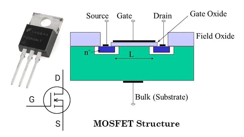
MOSFET stands for Metal-Oxide-Semiconductor Field-Effect Transistor. The name itself provides insights into its construction and operation:
- Metal: The gate terminal of the MOSFET is made of a metal or a heavily doped polycrystalline silicon.
- Oxide: A thin layer of oxide (usually silicon dioxide) insulates the gate from the underlying semiconductor material.
- Semiconductor: The body of the MOSFET is made of a semiconductor material, typically silicon, which can be either n-type or p-type.
- Field-Effect Transistor: MOSFETs operate by using an electric field to control the flow of current through the semiconductor material.
Understanding what MOSFET stands for helps in comprehending its structure and the fundamental principles behind its operation. This acronym encapsulates the essential elements that make MOSFETs unique and effective in their role within electronic circuits.
How Does a MOSFET Work?
To understand how a MOSFET works, it is crucial to look at its structure and the principles of operation. A MOSFET has three terminals: the source, the drain, and the gate. The source and drain are connected to the semiconductor material, while the gate is separated from the semiconductor by the thin oxide layer.
When a voltage is applied to the gate terminal, it creates an electric field that influences the conductivity of the semiconductor material between the source and drain. There are two main types of MOSFETs: n-channel and p-channel, each working differently based on the type of charge carriers (electrons for n-channel and holes for p-channel) that conduct current through the device.
N-Channel MOSFET
In an n-channel MOSFET, applying a positive voltage to the gate terminal attracts electrons towards the gate, creating a conductive channel between the source and drain. This allows current to flow from the drain to the source when a voltage is applied across these terminals. The amount of current flow is proportional to the gate voltage, allowing precise control over the current.
P-Channel MOSFET
Conversely, in a p-channel MOSFET, applying a negative voltage to the gate terminal repels electrons, creating a conductive channel for holes (positive charge carriers) between the source and drain. This allows current to flow from the source to the drain when a voltage is applied. The current flow is again proportional to the gate voltage, but in the opposite direction compared to n-channel MOSFETs.
The ability to control current flow with a small gate voltage makes MOSFETs highly efficient and suitable for various electronic applications, including switching, amplification, and signal modulation.
How to Use a MOSFET?
Using a MOSFET in an electronic circuit involves understanding its characteristics and proper configuration. Here are some general steps on how to use a MOSFET:
Selecting the Right MOSFET
- Determine the Type: Choose between n-channel and p-channel MOSFETs based on your circuit requirements.
- Voltage and Current Ratings: Ensure the MOSFET can handle the voltage and current levels in your application.
- On-Resistance (R<sub>DS(on)</sub>): Select a MOSFET with low on-resistance for efficient switching and minimal power loss.
Circuit Design
- Gate Drive Voltage: Ensure the gate drive voltage is sufficient to fully turn on the MOSFET. This voltage is typically specified in the MOSFET’s datasheet.
- Gate Resistor: Use a gate resistor to limit the inrush current and protect the MOSFET from damage during switching.
- Snubber Circuit: In high-speed switching applications, use a snubber circuit to dampen voltage spikes and protect the MOSFET.
Practical Application
- Switching: Use MOSFETs as electronic switches in digital circuits to control loads such as motors, LEDs, and relays.
- Amplification: In analog circuits, MOSFETs can amplify weak signals for applications like audio amplification and RF signal processing.
- Voltage Regulation: Utilize MOSFETs in power supply circuits for efficient voltage regulation and power conversion.
Safety Precautions
- Heat Dissipation: Ensure proper heat sinking to manage the thermal dissipation and prevent overheating.
- Static Protection: Handle MOSFETs with care to avoid static discharge damage, and use anti-static wristbands and mats.
Using MOSFETs effectively requires careful consideration of their electrical characteristics and proper circuit design to ensure reliable performance.
How to Test MOSFET?
Testing a MOSFET is essential to ensure it functions correctly in a circuit. Here are some methods to test a MOSFET:
Visual Inspection
- Physical Damage: Check for any visible signs of damage, such as burn marks or cracks on the MOSFET package.
- Solder Joints: Inspect the solder joints for proper connections and any signs of cold solder joints or corrosion.
Basic Electrical Testing
- Continuity Test: Use a multimeter to check for continuity between the source and drain terminals. There should be no continuity when the gate voltage is not applied.
- Gate Leakage Test: Measure the resistance between the gate and source terminals. A high resistance indicates no gate leakage, while a low resistance may indicate a faulty MOSFET.
How to Test a MOSFET With a Multimeter?
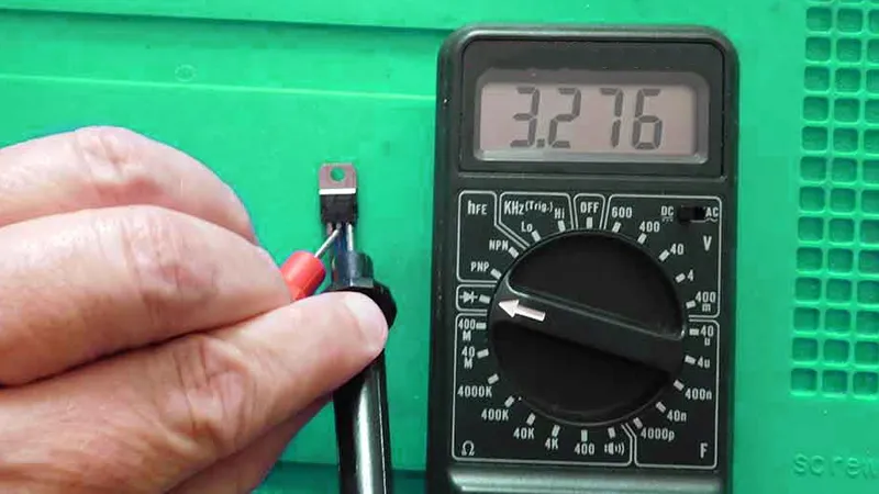
Testing a MOSFET with a multimeter is a straightforward process that involves checking the basic functionality of the device. Here’s a step-by-step guide:
Preparation
- Disconnect Power: Ensure the MOSFET is removed from the circuit or the circuit is powered off to avoid any damage or incorrect readings.
- Set Multimeter: Set the multimeter to the appropriate mode (diode test or resistance mode).
Testing Procedures
- Diode Test Mode:
- Connect the positive (red) probe to the drain and the negative (black) probe to the source of an n-channel MOSFET. The multimeter should not show any reading.
- Apply a positive voltage to the gate terminal using a power supply or a charged capacitor.
- Reconnect the multimeter probes. The multimeter should now show a low resistance, indicating the MOSFET is conducting.
- For a p-channel MOSFET, reverse the polarity of the probes and apply a negative gate voltage.
- Resistance Mode:
- Measure the resistance between the gate and source terminals. It should be very high (typically in the megaohms range).
- Measure the resistance between the drain and source terminals with the gate voltage applied and removed. A significant difference in resistance indicates proper switching.
Interpretation of Results
- Good MOSFET: High resistance between gate and source, and a significant change in resistance between drain and source with gate voltage applied.
- Faulty MOSFET: Low resistance between gate and source, or no change in resistance between drain and source with gate voltage applied.
Testing a MOSFET with a multimeter helps in quickly identifying whether the MOSFET is functioning correctly or needs replacement. It is a valuable skill for troubleshooting and maintaining electronic circuits.
Conclusion
MOSFETs play a pivotal role in modern electronics, offering versatility and efficiency in various applications. From understanding what MOSFET stands for to learning how to use and test these devices, this article has covered the essential aspects of MOSFETs.
Whether you are designing complex circuits or simply looking to enhance your understanding of electronic components, mastering MOSFETs is an invaluable skill.
By following the guidelines and testing procedures outlined, you can ensure the reliability and performance of MOSFETs in your electronic projects. As technology continues to advance, the knowledge of MOSFETs will remain a cornerstone of electronic engineering, driving innovation and progress in the field.