A diode, a fundamental electronic component, controls electrical current flow by allowing it to pass in one direction while blocking it in the other. This unidirectional behavior arises from the interaction between p-type and n-type semiconductor materials, which form a p-n junction.
This junction is key to the diode’s operation, making it essential for applications such as rectifying AC and protecting circuits. By understanding the mechanisms of this simple yet crucial device, one gains insight into its significant role in modern electronics.
What Is A Diode?
A diode resembles the image above and comes in various sizes. Typically, it features a black cylindrical body with a stripe at one end and leads extending from it for easy circuit connection. The striped end is the cathode, while the opposite end is the anode.
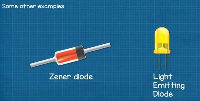
You can also find other types, like zener diodes or LEDs (light-emitting diodes). However, this article focuses solely on standard diodes, not these other forms.
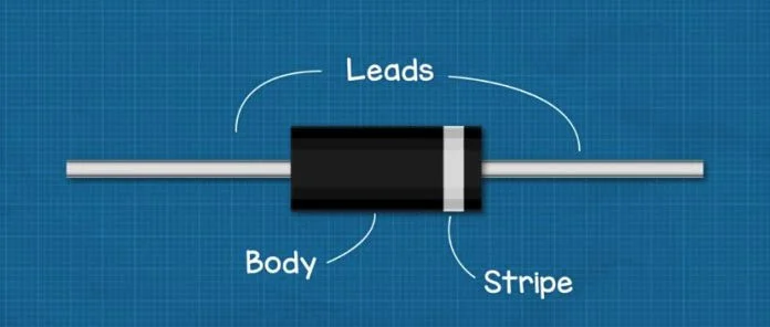
A diode lets current flow in only one direction.
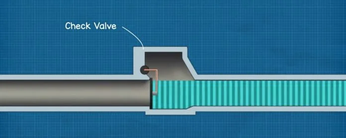
Imagine a water pipe with a swing valve installed. When water flows through the pipe, it pushes open the swing gate, allowing the water to continue flowing. However, if the water changes direction, it pushes the gate shut, preventing the flow. Similarly, current can only flow in one direction through a diode.
This concept is similar to how a diode works, as you use them to control the direction of current in a circuit.
Now, we’ve animated this using electron flow, where electrons move from negative to positive. However, in electronics engineering, the tradition is to use conventional flow, which is from positive to negative. Conventional current is probably easier to understand. You can use either, but it’s important to be aware of both and know which one we’re using.
When you connect a diode to a simple LED circuit like the one above, remember that the LED will only light up if you install the diode correctly. A diode allows current to flow in only one direction, so its installation determines whether it acts as a conductor or an insulator.
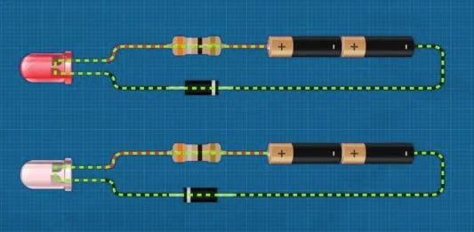
To make it act as a conductor, connect the striped end to the negative side and the black end to the positive side; this configuration is called forward bias. This setup allows current to flow. If you reverse the diode, it acts as an insulator and prevents current flow, a configuration known as reverse bias.

How Does A Diode Work?
You know that electricity is the flow of free electrons between atoms. Copper wires are used because copper has many free electrons, making it easy for electricity to pass through. Rubber insulates the copper wires and keeps you safe because rubber is an insulator, meaning its electrons are tightly held and cannot move between atoms.
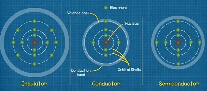
Consider a basic model of an atom in a metal conductor: the nucleus sits at the center, surrounded by orbital shells holding electrons. Each shell has a maximum capacity for electrons, and an electron needs a certain amount of energy to enter each shell. Electrons farthest from the nucleus have the most energy. The outermost shell, called the valence shell, in a conductor typically contains between 1 and 3 electrons.
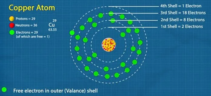
The nucleus holds the electrons in place, but there’s another shell known as the conduction band. If an electron reaches this band, it can break free from the atom and move to another. In a metal atom like copper, the conduction band and the valence shell overlap, making it easy for the electron to move.
In an insulator, the outermost shell is full, leaving little to no room for an electron to join. The nucleus has a tight grip on the electrons, and the conduction band is far away, so the electrons can’t escape. Therefore, electricity cannot flow through this material.
However, a material known as a semiconductor, like silicon, behaves differently. A semiconductor has one too many electrons in the outermost shell to act as a conductor, so it behaves like an insulator. Yet, because the conduction band is quite close, providing external energy can allow some electrons to gain enough energy to jump from the valence band to the conduction band and become free.
Therefore, this material can act as both an insulator and a conductor. Pure silicon has almost no free electrons, so engineers dope the silicon with small amounts of other materials to change its electrical properties.
This process is known as P-type and N-type doping. Combining these doped materials forms the diode.
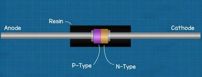
Inside the diode, you find two leads: the anode and the cathode, which connect to thin plates. Between these plates, there’s a layer of P-type doped silicon on the anode side and a layer of N-type doped silicon on the cathode side. The entire assembly is enclosed in resin to insulate and protect the materials.
Imagine the material hasn’t undergone doping yet, so it’s pure silicon inside. Each silicon atom is surrounded by four other silicon atoms. While each atom desires eight electrons in its valence shell, silicon atoms only possess four electrons in their valence shell. Therefore, they cleverly share an electron with their neighboring atom to achieve the desired eight electrons. This process is called covalent bonding.

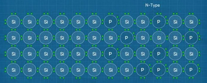
When you add N-type material like phosphorus, it replaces some of the silicon atoms. A phosphorus atom has five electrons in its valence shell. As the silicon atoms share electrons to reach their desired eight, they don’t need the extra one from phosphorus. This extra electron becomes free to move, increasing the material’s conductivity.
With P-type doping, you add a material like aluminum. This atom has only three electrons in its valence shell, so it can’t share an electron with each of its four neighbors, leaving one without. This creates a hole where an electron can occupy.
Now, you have two doped pieces of silicon: one with too many electrons (N-type) and one with too few electrons (P-type). When you join these two materials, they form a P-N junction. At this junction, a depletion region forms. Excess electrons from the N-type side move to fill the holes in the P-type side, creating a barrier with a buildup of electrons on one side and holes on the other.
The electrons are negatively charged, and the holes are considered positively charged. This buildup creates slightly negatively and positively charged regions, forming an electric field that prevents more electrons from moving across. The potential difference across this region is about 0.7V in typical diodes.

When you connect a voltage source across the diode, with the anode (P-Type) to the positive and the cathode (N-Type) to the negative, you create a forward bias that allows current to flow. Ensure the voltage source exceeds the 0.7V barrier; otherwise, the electrons can’t cross the junction.
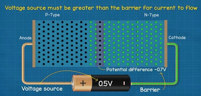
When you reverse the power supply, connecting the positive to the N-type cathode and the negative to the P-type anode, the holes move towards the negative side and the electrons move towards the positive side. This causes the barrier to expand, making the diode act as an insulator to prevent the flow of current.
Technical Details Of Diodes

In engineering drawings, diodes are represented by a symbol similar to the image above. The stripe on the diode body is shown as a vertical line on the symbol, and the arrow points in the direction of conventional current flow. When you examine a diode, you’ll notice numbers and letters on the body. These identifiers help you find the technical details online.
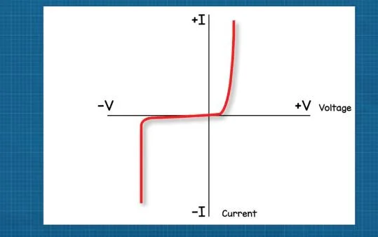
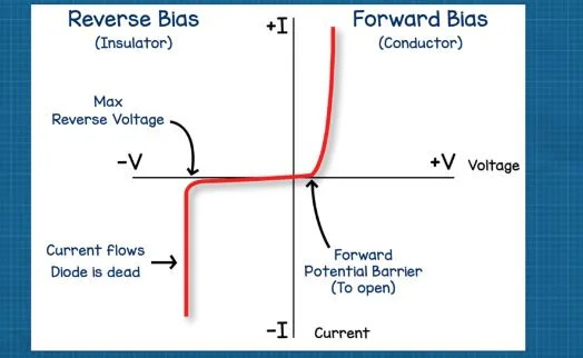
The diode has an I-V diagram like the one shown above. This diagram plots the current and voltage characteristics of a diode, forming a curved line. One side shows its performance as a conductor, while the other shows it acting as an insulator.
You can see that the diode only acts as an insulator up to a certain voltage difference. If you exceed this, it becomes a conductor, allowing current to flow. This can destroy the diode and possibly your circuit, so you must ensure the diode is properly sized for your application.
Similarly, the diode can handle only a certain voltage or current in the forward bias. Each diode has different specifications, so you need to look up the data to find these details. The diode requires a certain voltage level, typically around 0.6V, to allow current to flow in the forward bias. If the voltage applied is less than this, it won’t allow current to flow. However, as you increase the voltage beyond this threshold, the current flow will rapidly increase.
Diodes also cause a voltage drop in the circuit. For instance, when you add a diode to a simple LED circuit on a breadboard, you might measure a voltage drop of 0.71V.
Why We Use Diode?
Rectification
In a regular AC power supply, the current direction constantly changes. Since diodes allow electricity to flow in only one direction, they extract only the forward current from the AC current. This process is known as the rectifying action of the diode.
Radiowave Detection
Diodes help extract audio signals from radio waves, a process called wave detection. Radio waves combine high-frequency signals for communication with low-frequency signals like voice.
Voltage Control
Normally, diodes carry current in only one direction. However, when the voltage in the reverse direction exceeds a certain value, the current starts to flow. Even if the current increases, the voltage remains constant. This is called the breakdown phenomenon, and the voltage at which it occurs is the “breakdown voltage” or “Zener voltage.” You can use this phenomenon for voltage control with Zener diodes, which are designed specifically for this purpose.
Current Conversion
When light hits a PN junction, electrons near the junction on the N side shift, ensuring electricity flows while the light persists. This forms the basis of a solar cell. Without external voltage, it functions as a battery; with applied voltage, it acts as a diode. Certain diodes react to visible light, while others respond to invisible light, like those in infrared remote controls’ light-receiving parts.
How To Test A Diode?
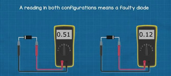
To test a diode, you’ll need a multimeter equipped with a diode test setting, denoted by a symbol resembling this. We highly recommend having a quality multimeter in your toolkit for learning and diagnosing issues.
Take your diode and multimeter. Connect the black wire to the end of the diode with a line, then attach the red wire to the opposite end. This should yield a reading on the screen.
For instance, the 1N4001 diode model may show a reading of 0.516V. This indicates the minimum voltage required to open the diode and allow current flow.
Now, if you reverse the leads connected to the diodes, you should see “OL” on the screen, indicating “outside limits.” This suggests the multimeter can’t complete the circuit, indicating the diode is functioning correctly.
If you receive a reading in both configurations, the component is faulty and shouldn’t be used.
To test a diode in a circuit for voltage drop, switch the multimeter to the DC voltage function. Place the black probe on the stripe end and the red probe on the black end. This should give you a voltage drop reading, for example, 0.71V.
Conclusion
To sum up, diodes are crucial in electronic circuits, controlling current flow and serving various functions. Their versatility drives technological advancements. Understanding diode principles empowers engineers and hobbyists to design and troubleshoot circuits effectively.
As technology evolves, so do diode applications, from early vacuum tube diodes to modern semiconductor ones, showcasing progress in electronics. Diodes hold endless potential to shape future technology.