H Bridge Integrated Circuit
An H-bridge integrated circuit (IC) is a compact electronic component that efficiently controls the direction and speed of a DC motor. It’s essentially a collection of switches configured in a “H” shape, hence the name. By strategically activating these switches, the IC can reverse the polarity of the voltage applied to the motor, allowing it to spin in either direction.
Comparator Integrated Circuit Using Op Amp
Op-Amps in Action: Unlock Comparator Functionality! Explore how to leverage the versatility of op-amps to create basic comparator circuits. Download our free SPICE simulation files and experiment with comparator configurations using readily available components!
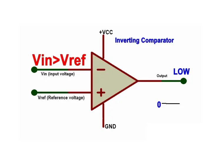
Comparator Circuit Diagram
A comparator circuit diagram visually represents the electrical components and connections that make up a comparator circuit. It helps understand how the circuit functions and how different parts interact to compare two input voltages.
Comparator Integrated Circuit Applications
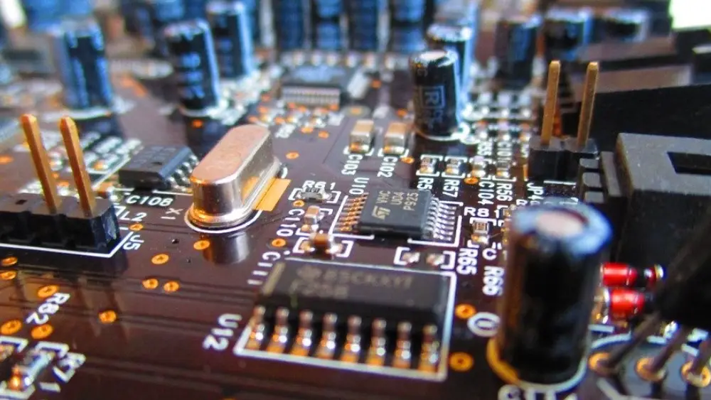
Comparator Integrated Circuit
Comparator ICs excel at comparing two analog voltages and outputting a digital signal based on the comparison. This makes them ideal for applications like:
- Threshold detection: Triggering alarms or actions when a voltage level exceeds or falls below a set point (e.g., overvoltage/undervoltage protection in circuits).
- Signal level monitoring: Monitoring the strength of a signal and taking action based on its intensity (e.g., signal strength indicator in a radio receiver).
Signal Shaping and Pulse Generation
Comparators can be used to convert analog signals into digital pulses based on voltage thresholds. This functionality is used in:
- Analog-to-Digital Converters (ADCs): A crucial component in ADCs, comparators help convert continuously varying analog signals into discrete digital values.
- Pulse Width Modulation (PWM) generation: Comparators can be used to create digital square waves with varying pulse widths based on an analog input signal. This is used for controlling motor speeds, LED brightness, etc.
Zero-Crossing Detection
Comparator ICs can be configured to detect when an analog signal crosses a specific voltage level, typically zero volts. This is useful in applications like:
- AC signal processing: Identifying the zero-crossing points of an AC waveform is crucial for tasks like signal rectification and synchronization.
- Phase detection: Comparators can be used to compare the phases of two AC signals, finding the difference between their zero-crossing points.
High-Speed Decision Making
Due to their fast response times, comparators can be used to make rapid decisions based on analog input signals. This is used in:
- Logic circuits: Comparators can be used as building blocks in logic circuits, performing basic comparisons like “greater than” or “less than” to generate digital outputs.
- Sensor interfaces: In some sensor applications, comparators can be used to convert sensor outputs (often voltage-based) into digital signals for further processing.
H Bridge Integrated Circuit FAQs
What is an H-bridge IC?
An H-bridge IC is a specialized integrated circuit designed to control the direction and speed of a DC motor. It’s essentially a miniaturized version of a traditional H-bridge circuit, offering a convenient and efficient solution for various applications.
What is the connection of the H-bridge circuit?
An H-bridge circuit typically connects to:
Input:
- Power supply: This provides the voltage for driving the motor.
- Control signals: These determine the state of the H-bridge switches (usually from a microcontroller or other control circuit).
Output:
- Motor terminals: The H-bridge switches connect to the motor’s terminals, allowing current to flow in either direction.
Additional Components (often included):
- Diodes: These are used to protect the H-bridge switches from voltage spikes when the motor’s inductance is turned off.
- Capacitors: These can be used to filter power supply noise and stabilize the voltage.
Key points to remember:
- Only two switches should be turned on at a time to avoid short-circuiting the power supply.
- The choice of switches (transistors, MOSFETs, etc.) depends on the required current, voltage, and switching speed.
- Proper heat dissipation is essential for high-power applications.
Would you like to see a more detailed diagram or learn about specific H-bridge ICs?