Electronic component symbols are utilized to indicate the components in circuit diagrams. Each electronic component has a standard symbol that uniquely represents it.
This article provides an overview of common electronic components along with their corresponding symbols.
What Are Electronic Component Symbols?
Electronic component symbols are graphical representations used to depict various electronic components in circuit diagrams and schematics.
These symbols provide a standardized and concise way to represent components such as resistors, capacitors, diodes, transistors, and integrated circuits. Each symbol is designed to convey specific information about the component’s functionality, polarity, and electrical characteristics.
Importance of Electronic Components Symbols
The importance of electronic component symbols cannot be overstated in the realm of electronics. These symbols serve as a universal language, facilitating communication and understanding among engineers, technicians, and enthusiasts worldwide. Here are several key reasons why electronic component symbols are essential:
Standardization:
Electronic symbols provide a standardized way to represent various components, ensuring consistency across different circuit diagrams and schematics. This standardization streamlines communication and collaboration in electronics design, manufacturing, and maintenance.
Clarity and Precision:
By using symbols to represent components such as resistors, capacitors, and transistors, complex circuit designs can be depicted clearly and precisely. This clarity helps engineers and technicians analyze circuits, identify components, and troubleshoot issues effectively.
Efficiency: Electronic symbols enable engineers to convey vast amounts of information quickly and efficiently. Instead of writing out lengthy component names or descriptions, engineers can simply use symbols, saving time and reducing the risk of errors.
Global Understanding:
Since electronic symbols follow international standards, they transcend language barriers. Engineers and technicians from different countries and backgrounds can interpret circuit diagrams accurately, fostering global collaboration and innovation in the field of electronics.
Education and Training:
Electronic symbols play a crucial role in education and training programs for aspiring engineers and technicians. By learning to interpret these symbols, students develop essential skills for understanding and designing electronic circuits, preparing them for careers in various industries.
Troubleshooting and Maintenance:
In maintenance and repair scenarios, electronic symbols are invaluable for identifying faulty components and understanding circuit functionality. Technicians can refer to circuit diagrams and schematics to pinpoint issues and implement solutions efficiently.
Documentation and Archiving:
Electronic symbols are used extensively in the documentation and archiving of electronic designs and projects. Circuit diagrams and schematics, annotated with symbols, serve as valuable reference materials for future projects, upgrades, and modifications.
Importance of Standardization in Electronic Symbols
Standardization in electronic symbols is of paramount importance in the field of electronics for several reasons:
Consistency: Standardized symbols ensure consistency in circuit diagrams and schematics across different industries, companies, and regions. Engineers and technicians can easily interpret and understand circuit diagrams regardless of where they were created or who created them.
Interoperability: Standard symbols promote interoperability among electronic devices and systems. Components designed and manufactured by different companies can be integrated seamlessly into larger systems without compatibility issues, reducing development time and costs.
Communication: Standard symbols serve as a universal language for communicating complex circuit designs and configurations. Engineers, technicians, and designers from diverse backgrounds can effectively communicate and collaborate on projects using standardized symbols, facilitating efficient teamwork and problem-solving.
Education and Training: Standard symbols simplify the teaching and learning process in electronics education and training programs. Students and professionals can easily grasp fundamental concepts and principles when presented with standardized symbols, accelerating their learning curve and enabling them to apply their knowledge effectively.
Quality and Reliability: Standardization promotes quality and reliability in electronic systems and devices. By adhering to established symbol standards, manufacturers can ensure that their products meet industry-wide specifications and requirements, resulting in higher quality and more reliable electronic products.
Ease of Maintenance and Repair: Standard symbols make maintenance and repair tasks easier and more efficient. Technicians and service personnel can quickly identify and replace faulty components by referencing standardized circuit diagrams, reducing downtime and minimizing the risk of errors during repair procedures.
Globalization: In an increasingly globalized world, standardized symbols facilitate communication and collaboration among multinational teams and companies. Engineers and technicians from different countries and cultural backgrounds can work together seamlessly, leveraging standardized symbols as a common reference point for their discussions and interactions.
In summary, standardization in electronic symbols is essential for ensuring consistency, interoperability, communication, education, quality, reliability, ease of maintenance, and globalization in the field of electronics. By adopting and adhering to standardized symbol conventions, the electronics industry can achieve greater efficiency, innovation, and success in designing, manufacturing, and deploying electronic systems and devices.
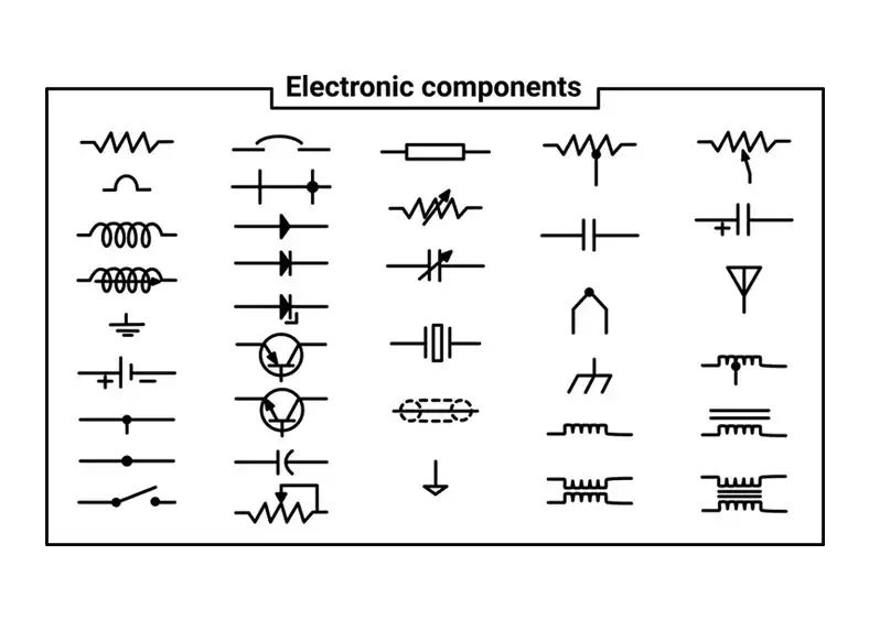
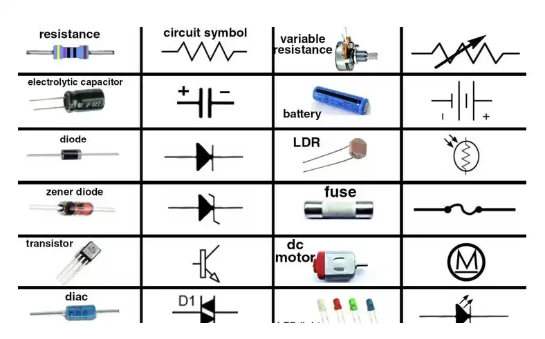
Commonly Used Schematic Symbols of Electronic Components
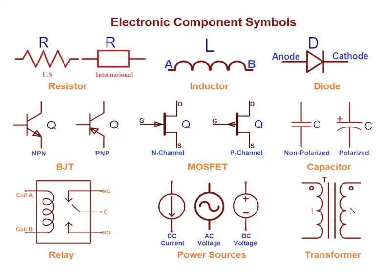
Here is list of electronic components symbols in the following:
Resistors
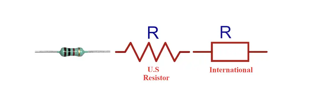
Resistors are fundamental components in electronics, offering resistance to the flow of electric current. Their symbols typically consist of rectangular shapes with zigzag lines.
Capacitors
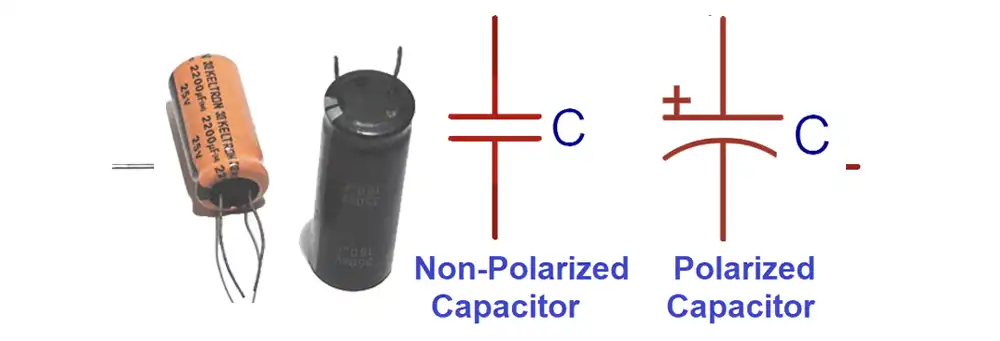
Capacitors store and release electrical energy. Their symbols vary depending on the type of capacitor, whether polarized or non-polarized.
Inductors
Inductors resist changes in current flow and are represented by coil-like symbols.
Diodes
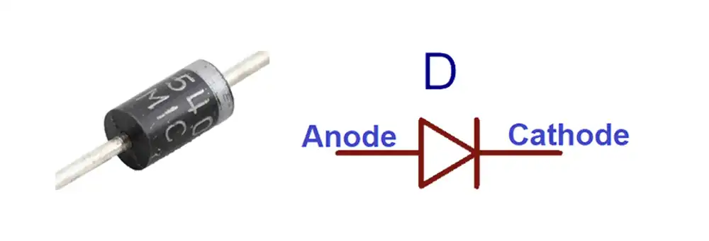
Diodes allow current to flow in one direction and block it in the opposite direction. Their symbols include arrows indicating the direction of current flow.
Transistors
Transistors amplify or switch electronic signals and come in various types such as Bipolar Junction Transistors (BJTs) and Field Effect Transistors (FETs). Their symbols depict the transistor’s structure and functionality.
Integrated Circuits
Integrated Circuits (ICs) contain multiple electronic components within a single package. Their symbols vary depending on the specific IC type, such as operational amplifiers or microcontrollers.
Here is a list of common electronic component symbols along with their brief descriptions:
- Resistor: Symbolized by a zigzag line, representing resistance to the flow of electric current within the circuit.
- Capacitor: Depicted by two parallel lines or plates separated by a gap, indicating the capacitor’s ability to store and release electrical energy.
- Inductor: Represented by a coil or loop, denoting the inductor’s ability to resist changes in current flow and store energy in a magnetic field.
- Diode: Typically shown as a triangle with an arrow pointing towards the direction of current flow, signifying the diode’s function of allowing current to flow in one direction while blocking it in the opposite direction.
- Transistor: Comes in various types such as Bipolar Junction Transistors (BJTs) and Field Effect Transistors (FETs). The symbols for BJTs include two intersecting lines, while FETs are represented by various shapes indicating their structure and functionality.
- Integrated Circuit (IC): Denoted by a rectangle with pins extending from its sides, representing multiple electronic components integrated into a single package. Different types of ICs, such as operational amplifiers and microcontrollers, have unique symbols.
These symbols serve as a visual language that allows engineers, technicians, and enthusiasts to interpret circuit diagrams accurately and efficiently. Understanding and recognizing these symbols is essential for designing, analyzing, and troubleshooting electronic circuits in various applications.
Schematic Symbols of Electronic Components
Schematic symbols of electronic components are graphical representations used in circuit diagrams and schematics to depict various electronic components and their connections within a circuit. These symbols provide a standardized and concise way to communicate complex circuit designs and configurations to engineers, technicians, and enthusiasts. Understanding these symbols is essential for designing, analyzing, and troubleshooting electronic circuits effectively.
Here are some common schematic symbols of electronic components along with brief explanations:
- Resistor: Symbolized by a zigzag line, representing resistance to the flow of electric current within the circuit.
- Capacitor: Depicted by two parallel lines or plates separated by a gap, indicating the capacitor’s ability to store and release electrical energy.
- Inductor: Represented by a coil or loop, denoting the inductor’s ability to resist changes in current flow and store energy in a magnetic field.
- Diode: Typically shown as a triangle with an arrow pointing towards the direction of current flow, signifying the diode’s function of allowing current to flow in one direction while blocking it in the opposite direction.
- Transistor: Comes in various types such as Bipolar Junction Transistors (BJTs) and Field Effect Transistors (FETs). The symbols for BJTs include two intersecting lines, while FETs are represented by various shapes indicating their structure and functionality.
- Integrated Circuit (IC): Denoted by a rectangle with pins extending from its sides, representing multiple electronic components integrated into a single package. Different types of ICs, such as operational amplifiers and microcontrollers, have unique symbols.
These symbols are arranged within circuit diagrams to illustrate the connections and interactions between components accurately. Engineers and technicians use these diagrams to design circuits, analyze their functionality, and diagnose problems during troubleshooting.
Here’s a table summarizing some common schematic symbols of electronic components:
| Component | Symbol | Description |
|---|---|---|
| Resistor | Zigzag line | Represents resistance to current flow |
| Capacitor | Parallel lines | Indicates the ability to store and release electrical energy |
| Inductor | Coil or loop | Represents resistance to changes in current flow and energy storage in a magnetic field |
| Diode | Triangle | Allows current flow in one direction, blocks it in the other direction |
| Transistor | Various shapes | Amplifies or switches electronic signals |
| Integrated Circuit | Rectangle with pins | Contains multiple components within a single package |
Understanding and interpreting these symbols is crucial for anyone working with electronic circuits, as they provide a universal language for communicating complex circuit designs effectively.
Electronic Components Symbols and Abbreviations
Here is a list of common electronic component symbols, their abbreviations, and brief descriptions:
- Resistor (R): Symbolized by a zigzag line, representing resistance to the flow of electric current within the circuit.
- Capacitor (C): Depicted by two parallel lines or plates separated by a gap, indicating the capacitor’s ability to store and release electrical energy.
- Inductor (L): Represented by a coil or loop, denoting the inductor’s ability to resist changes in current flow and store energy in a magnetic field.
- Diode (D): Typically shown as a triangle with an arrow pointing towards the direction of current flow, signifying the diode’s function of allowing current to flow in one direction while blocking it in the opposite direction.
- Transistor (Q): Comes in various types such as Bipolar Junction Transistors (BJTs) and Field Effect Transistors (FETs). The symbols for BJTs include two intersecting lines, while FETs are represented by various shapes indicating their structure and functionality.
- Integrated Circuit (IC): Denoted by a rectangle with pins extending from its sides, representing multiple electronic components integrated into a single package. Different types of ICs, such as operational amplifiers and microcontrollers, have unique symbols.
Here’s a table summarizing electronic component symbols, their abbreviations, and descriptions:
| Component | Abbreviation | Symbol | Description |
|---|---|---|---|
| Resistor | R | Zigzag line | Represents resistance to current flow |
| Capacitor | C | Parallel lines | Indicates the ability to store and release electrical energy |
| Inductor | L | Coil or loop | Represents resistance to changes in current flow and energy storage in a magnetic field |
| Diode | D | Triangle | Allows current flow in one direction, blocks it in the other direction |
| Transistor | Q | Various shapes | Amplifies or switches electronic signals |
| Integrated Circuit | IC | Rectangle with pins | Contains multiple components within a single package |
Understanding these symbols and their abbreviations is essential for interpreting circuit diagrams accurately and effectively designing electronic circuits.
Identifying Electronic Components Circuit Symbols and Functions
Identifying electronic component circuit symbols and understanding their functions is crucial for anyone working with electronics. Here are some common electronic components, their symbols, and their functions:
- Resistor (R):
- Symbol: Zigzag line.
- Function: Offers resistance to the flow of electric current, controlling the current in a circuit and voltage levels.
- Capacitor (C):
- Symbol: Two parallel lines or plates separated by a gap.
- Function: Stores and releases electrical energy, filtering signals, and smoothing voltage fluctuations.
- Inductor (L):
- Symbol: Coil or loop.
- Function: Resists changes in current flow, storing energy in a magnetic field, and blocking high-frequency signals in a circuit.
- Diode (D):
- Symbol: Triangle with an arrow pointing towards the direction of current flow.
- Function: Allows current to flow in one direction while blocking it in the opposite direction, often used for rectification and voltage regulation.
- Transistor (Q):
- Symbol: Various shapes depending on the type (e.g., BJTs, FETs).
- Function: Amplifies or switches electronic signals, controlling the flow of current in a circuit, and serving as the building block for digital circuits.
- Integrated Circuit (IC):
- Symbol: Rectangle with pins extending from its sides.
- Function: Contains multiple electronic components within a single package, such as microprocessors, operational amplifiers, and memory chips, performing various functions depending on the specific IC type.
- Light Emitting Diode (LED):
- Symbol: Similar to a diode but with arrows pointing away from it (indicating light emission).
- Function: Emits light when current flows through it in the forward direction, commonly used for indicators, displays, and illumination purposes.
- Voltage Regulator:
- Symbol: Often represented as a rectangle with three terminals (input, output, and ground).
- Function: Maintains a constant output voltage despite changes in input voltage or load current, ensuring stable power supply for electronic circuits.
- Switch:
- Symbol: Usually represented as a gap in a circuit line with a toggle or push-button.
- Function: Controls the flow of current in a circuit by opening or closing the circuit path, allowing users to turn electronic devices on or off.
Understanding these symbols and their functions enables engineers, technicians, and hobbyists to design, analyze, and troubleshoot electronic circuits effectively. Whether it’s for building simple projects or designing complex systems, familiarity with electronic component symbols is essential in the world of electronics.
Circuit Symbols of Electronic Components
Here’s a list of common circuit symbols of electronic components along with their brief descriptions:
Resistor (R):
Symbol: Zigzag line.
Description: Represents resistance to the flow of electric current within the circuit.
Capacitor (C):
Symbol: Two parallel lines or plates separated by a gap.
Description: Indicates the ability to store and release electrical energy.
Inductor (L):
Symbol: Coil or loop.
Description: Represents resistance to changes in current flow and energy storage in a magnetic field.
Diode (D):
Symbol: Triangle with an arrow pointing towards the direction of current flow.
Description: Allows current to flow in one direction while blocking it in the opposite direction.
Transistor (Q):
Symbol: Various shapes depending on the type (e.g., BJTs, FETs).
Description: Amplifies or switches electronic signals, controlling the flow of current in a circuit.
Integrated Circuit (IC):
Symbol: Rectangle with pins extending from its sides.
Description: Contains multiple electronic components within a single package, performing various functions depending on the specific IC type.
Light Emitting Diode (LED):
Symbol: Similar to a diode but with arrows pointing away from it.
Description: Emits light when current flows through it in the forward direction.
Voltage Regulator:
Symbol: Often represented as a rectangle with three terminals (input, output, and ground).
Description: Maintains a constant output voltage despite changes in input voltage or load current.
Switch:
Symbol: Usually represented as a gap in a circuit line with a toggle or push-button.
Description: Controls the flow of current in a circuit by opening or closing the circuit path.
Here’s a table summarizing the circuit symbols of electronic components:
| Component | Symbol | Description |
|---|---|---|
| Resistor (R) | Zigzag line | Represents resistance to current flow |
| Capacitor (C) | Two parallel lines | Indicates the ability to store and release electrical energy |
| Inductor (L) | Coil or loop | Represents resistance to changes in current flow and energy storage in a magnetic field |
| Diode (D) | Triangle with arrow | Allows current flow in one direction, blocks it in the other direction |
| Transistor (Q) | Various shapes | Amplifies or switches electronic signals |
| Integrated Circuit (IC) | Rectangle with pins | Contains multiple components within a single package |
| LED | Similar to diode with arrows | Emits light when current flows through it |
| Voltage Regulator | Rectangle with three terminals | Maintains a constant output voltage |
| Switch | Gap in circuit line | Controls the flow of current in a circuit |
Understanding these symbols is essential for interpreting circuit diagrams accurately and effectively designing electronic circuits.
Capacitor Symbols and Their Variations
Capacitor symbols play a vital role in circuit diagrams, representing the different types and characteristics of capacitors used in electronic circuits. Here’s a breakdown of capacitor symbols and their variations:
Standard Capacitor Symbol:
Symbol: Two parallel lines or plates separated by a gap.
Description: This symbol represents a standard capacitor, indicating its ability to store and release electrical energy.
Polarized Capacitor Symbol:
Symbol: Similar to the standard capacitor symbol but with one plate having a curved line.
Description: Polarized capacitors, such as electrolytic capacitors, have polarity and must be connected in the correct orientation to prevent damage. The curved line indicates the positive terminal.
Non-Polarized Capacitor Symbol:
Symbol: Two parallel lines or plates without any curved line.
Description: Non-polarized capacitors, like ceramic or film capacitors, do not have polarity and can be connected in either direction in a circuit.
Variable Capacitor Symbol:
Symbol: Two parallel lines or plates with an arrow or a curved line attached to one plate.
Description: Variable capacitors, also known as trimmer capacitors, have a capacitance that can be adjusted manually or electronically. The arrow or curved line indicates the adjustable nature of the capacitor.
Trimmer Capacitor Symbol:
Symbol: Similar to the standard capacitor symbol but with an additional arrow or curved line.
Description: Trimmer capacitors are small, adjustable capacitors used for fine-tuning circuits during assembly or calibration. The arrow or curved line signifies the adjustable nature of the capacitor.
Tantalum Capacitor Symbol:
Symbol: Similar to the standard capacitor symbol but with a “+” sign near one plate.
Description: Tantalum capacitors are polarized capacitors known for their high capacitance and compact size. The “+” sign indicates the positive terminal of the capacitor.
Mica Capacitor Symbol:
Symbol: Two parallel lines or plates with the letter “M” inside one of the plates.
Description: Mica capacitors are high-quality capacitors known for their stability and low loss. The “M” inside one of the plates denotes the capacitor’s construction using mica as the dielectric material.
Understanding these variations in capacitor symbols is essential for accurately depicting capacitors in circuit diagrams and ensuring proper circuit functionality. Whether it’s choosing the right type of capacitor for a specific application or troubleshooting circuit issues, knowing the capacitor symbols and their variations is fundamental in electronics design and maintenance.
Power Electronics Components Symbols
Power electronics components play a crucial role in the control and conversion of electrical power in various applications.
Here are some common power electronics components symbols along with a chart summarizing them:
Diode (Power Diode):
Symbol: Similar to a standard diode symbol but often thicker or with additional markings.
Description: Power diodes are used for rectification and voltage regulation in power supply circuits.
Thyristor (SCR – Silicon Controlled Rectifier):
Symbol: Consists of three layers with a control terminal (gate).
Description: Thyristors are semiconductor devices used for high-power switching and control applications, including motor drives, lighting control, and power supplies.
Power MOSFET (Metal-Oxide-Semiconductor Field-Effect Transistor):
Symbol: Similar to a standard MOSFET symbol but often thicker or with additional markings.
Description: Power MOSFETs are used for high-speed switching and power amplification in various power electronics applications, such as motor control and power converters.
IGBT (Insulated Gate Bipolar Transistor):
Symbol: Combination of MOSFET and bipolar transistor symbols.
Description: IGBTs combine the advantages of MOSFETs (high input impedance) and bipolar transistors (high current-carrying capability) and are widely used in high-power switching applications, including motor drives, inverters, and power supplies.
Power Resistor:
Symbol: Zigzag line similar to a standard resistor symbol but often thicker or with additional markings.
Description: Power resistors are designed to handle high power levels and dissipate heat efficiently in power electronics circuits.
Transformer:
Symbol: Two coils of wire (primary and secondary) connected by a core.
Description: Transformers are used to step up or step down voltage levels in power electronics circuits, facilitating power distribution and voltage conversion.
Power Inductor:
Symbol: Similar to a standard inductor symbol but often thicker or with additional markings.
Description: Power inductors are designed to handle high currents and store energy in magnetic fields, used in applications such as switching regulators and power amplifiers.
Diode Symbols and Their Functions
Diodes allow current flow in one direction while blocking it in the opposite direction. Light Emitting Diodes (LEDs) are indicated by a triangle with arrows pointing away, while Zener diodes have additional markings to denote their voltage breakdown.
Transistor Symbols and Their Types
Transistors serve as amplifiers or switches in electronic circuits and come in various configurations. Bipolar Junction Transistors (BJTs) are represented by two intersecting lines, while Field Effect Transistors (FETs) have different symbols indicating their structure.
Symbols for Integrated Circuits (ICs)
Integrated Circuits (ICs) contain multiple electronic components within a single package, and their symbols vary depending on the specific IC type. Operational amplifiers and microcontrollers, for instance, have unique symbols representing their functionality.
Conclusion
Electronic component symbols play a crucial role in the design, analysis, and troubleshooting of electronic circuits. By understanding and utilizing these symbols effectively, engineers and enthusiasts can navigate the intricate world of electronics with precision and clarity.
FAQs
Why are electronic symbols important in circuit design?
Electronic symbols provide a standardized way to represent components, aiding in circuit design, analysis, and communication.
How do I learn to interpret electronic symbols?
You can learn to interpret electronic symbols through online resources, textbooks, and practical experience with circuit diagrams.
What challenges do engineers face in using electronic symbols?
Engineers may encounter challenges such as symbol standardization issues, evolving technologies, and regional variations in symbol conventions.
Are there any universal electronic symbol standards?
While efforts towards standardization exist, there may be variations in electronic symbol conventions based on industry practices and regional preferences.
What is the significance of future trends in electronic symbols?
Future trends in electronic symbols may reflect advancements in technology and the need to represent increasingly complex components and functionalities accurately.