As an experienced supplier of electronic components, I often encounter questions from customers regarding the basic principles of capacitors, particularly the electric field in a capacitor.
This article aims to provide a comprehensive understanding of the electric field within a capacitor, its importance in various applications, and the factors that influence its behavior.
Whether you are a seasoned engineer or a beginner in electronics, this guide will help you grasp the essential concepts and their practical implications.
Basics of Capacitors
What Are Capacitors
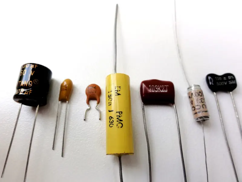
A capacitor is a fundamental passive component in electronic circuits, designed to store electrical energy in an electric field. It consists of two conductive plates separated by an insulating material known as a dielectric. The primary function of a capacitor is to store and release electrical energy, making it indispensable in a wide range of applications, from power supplies to signal processing.
Capacitor Working Principle
When a voltage is applied across the plates of a capacitor, an electric field is established between the plates. This electric field stores the electrical energy, which can be released when the capacitor discharges. The amount of energy stored depends on the capacitance of the capacitor, which is determined by the physical dimensions and the dielectric material.
The Concept of Electric Field
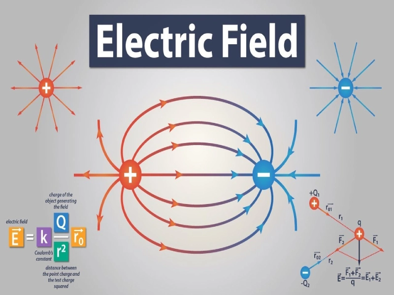
An electric field is a region around a charged particle where other charged particles experience a force. The electric field is a vector quantity, meaning it has both magnitude and direction. It can be visualized using electric field lines, which indicate the direction of the force that would be exerted on a positive test charge placed in the field.
Properties of Electric Fields
- Direction: The electric field lines point from positive charges to negative charges.
- Strength: The strength of the electric field is proportional to the number of field lines per unit area.
Electric Field in a Capacitor
Formation of Electric Field
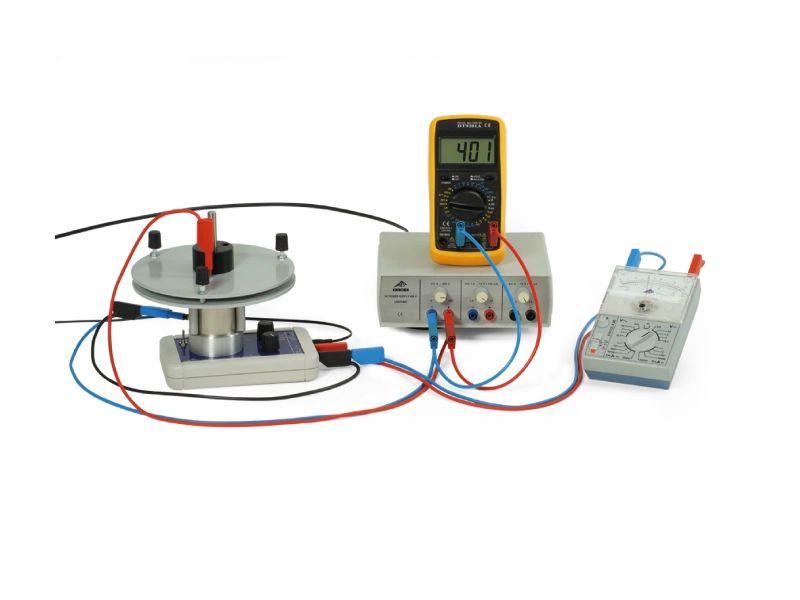
When a voltage is applied across the plates of a capacitor, an electric field is established between the plates. This electric field is responsible for storing the electrical energy in the capacitor. The strength of the electric field is directly proportional to the voltage applied and inversely proportional to the distance between the plates.
Electric Field of Parallel Plate Capacitor
One of the most common types of capacitors is the parallel plate capacitor. In a parallel plate capacitor, the electric field is uniform between the plates, assuming the plates are large enough compared to the separation distance. The electric field E in a parallel plate capacitor can be calculated using the formula:

where V is the voltage across the plates and d is the distance between them.
What is the Electric Field Strength Inside the Capacitor
The electric field inside a parallel-plate capacitor is uniform and perpendicular to the plates.1 This means that the electric field has the same magnitude and direction at all points between the plates.2
The magnitude of the electric field, E, can be calculated using the following formula:
E = σ / ε₀
Where:
Eis the electric field strength in volts per meter (V/m)σis the surface charge density (charge per unit area) on the plates in coulombs per square meter (C/m²)ε₀is the permittivity of free space (approximately 8.85 × 10⁻¹² F/m)
This formula shows that the electric field strength between the plates is directly proportional to the surface charge density and inversely proportional to the permittivity of free space.3
Factors Affecting the Electric Field in a Capacitor
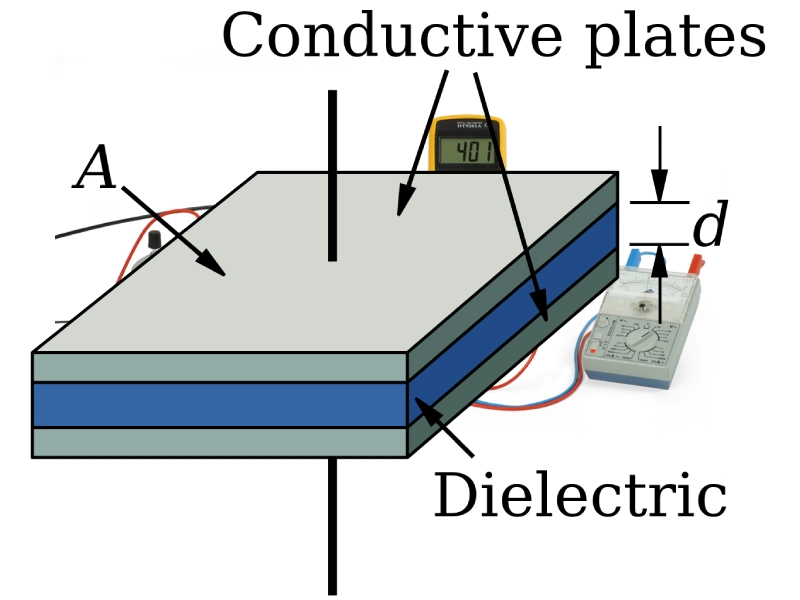
Plate Area
The area of the plates affects the capacitance and, consequently, the electric field. Larger plate areas result in higher capacitance and a more uniform electric field.
Plate Separation
The distance between the plates determines the strength of the electric field. A smaller separation distance results in a stronger electric field for a given voltage.
Dielectric Material
The dielectric material between the plates plays a crucial role in determining the electric field. The dielectric constant (κ) of the material affects the capacitance and the electric field strength. A higher dielectric constant increases the capacitance and reduces the electric field strength for a given voltage.
Temperature
Temperature can affect the properties of the dielectric material, leading to changes in the electric field. For example, some dielectrics may exhibit reduced permittivity at higher temperatures, which can decrease the electric field strength.
Parallel Plate Capacitor Electric Field
Understanding the Basics
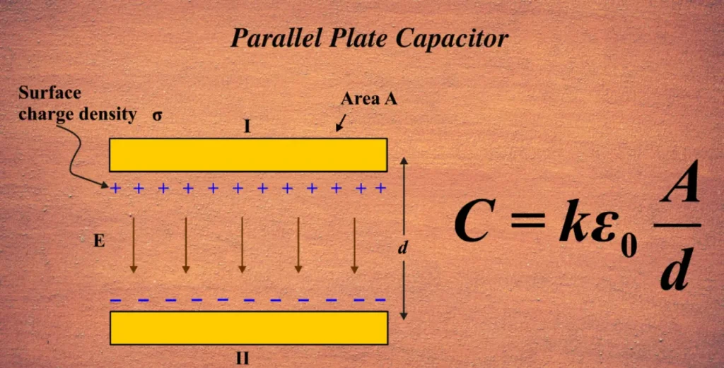
A parallel-plate capacitor consists of two conductive plates separated by a dielectric material (an insulator). When a voltage is applied across the plates, electric charge accumulates on the plates, creating an electric field between them.
Electric Field Strength
The electric field between the plates of an ideal parallel-plate capacitor is uniform and perpendicular to the plates. The magnitude of this electric field, denoted by E, can be calculated using the following formula:
E = σ / ε₀
Where:
Eis the electric field strength in volts per meter (V/m)σis the surface charge density (charge per unit area) on the plates in coulombs per square meter (C/m²)ε₀is the permittivity of free space (approximately 8.85 × 10⁻¹² F/m)
Applications of Capacitors
Energy Storage
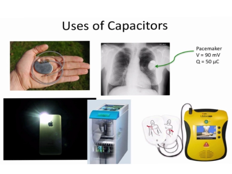
Capacitors are used to store electrical energy, which can be released quickly when needed. This makes them ideal for applications such as backup power supplies and energy storage in power electronics.
Filtering
Capacitors are used in filter circuits to remove unwanted frequencies from signals. They can block DC components while allowing AC components to pass through, making them essential in analog and digital signal processing.
Coupling and Decoupling
In circuits, capacitors are used to couple or decouple signals. Coupling capacitors allow AC signals to pass between stages while blocking DC components, while decoupling capacitors provide a low-impedance path to ground for high-frequency noise.
Signal Processing
Capacitors are used in various signal processing applications, such as timing circuits, oscillators, and integrators.
Conclusion
Understanding the electric field in a capacitor is crucial for anyone working with electronic components. From the basic principles to the practical applications, this article has covered the essential aspects of the electric field in a capacitor, including the electric field in a parallel plate capacitor and the factors that influence its behavior.
As an electronic component supplier, I hope this guide provides valuable insights and helps you make informed decisions in your work.
If you have any further questions or need more detailed information, feel free to reach out.
What is the electric field in a capacitor?
The electric field in a capacitor refers to the electric field formed between the two plates when a voltage is applied across them.
This field is created by the charges on the plates and stores electrical energy. The direction of the electric field is from the positively charged plate to the negatively charged plate.
How do you calculate the electric field strength between the plates of a capacitor?
The electric field strength between the plates of a capacitor can be calculated using the formula:
where V is the voltage across the plates and d is the distance between the plates. This formula is applicable to parallel plate capacitors, where the electric field is uniform between the plates.
What is the direction of the electric field in a capacitor?
The direction of the electric field in a capacitor is always from the positively charged plate to the negatively charged plate.
This is because the electric field lines point from positive charges to negative charges.
How do you measure the electric field strength in a capacitor?
To measure the electric field strength in a capacitor, you can follow these steps:
1.Use a voltmeter to measure the voltage V across the capacitor.
2.Measure the distance d between the plates.
3.Use the formula to calculate the electric field strength.
How does the dielectric material affect the electric field in a capacitor?

The dielectric material significantly affects the electric field in a capacitor. The dielectric constant κ of the material influences the capacitance, which in turn affects the electric field strength.
Specifically, the dielectric increases the capacitance, reducing the electric field strength for a given voltage. The formula for the electric field in a capacitor with a dielectric is:
where κ is the dielectric constant.
Why does the electric field in a capacitor distort at the edges of the plates?
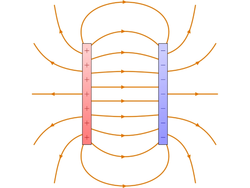
In an idealized parallel plate capacitor model, the electric field is assumed to be uniform between the plates.
However, in reality, the electric field distorts at the edges of the plates, a phenomenon known as the “fringing effect.” The fringing effect occurs due to the following reasons:
1.Expansion of Electric Field Lines: At the edges of the plates, the electric field lines do not remain strictly perpendicular to the plates but instead spread outwards. This causes the electric field strength at the edges to be slightly weaker than in the central region.
2.Geometric Influence: The finite size and edge shape of the plates cause the electric field lines to diverge at the edges rather than remaining perfectly parallel.
3.Non-uniform Charge Distribution: At the edges of the plates, the charge distribution is not uniform, leading to the bending and spreading of the electric field lines.
The fringing effect can impact the performance of the capacitor, especially in high-precision applications.
To minimize the fringing effect, the following measures can be taken:
1.Increase Plate Area: Increasing the area of the plates reduces the relative impact of the fringing effect on the total electric field.
2.Decrease Plate Separation: Reducing the separation between the plates enhances the uniformity of the electric field.
3.Use Shielding: Adding shielding around the plates can effectively suppress the fringing effect.