Ceramic capacitors are ubiquitous components in electronic circuits, playing a crucial role in filtering, coupling, and energy storage. However, their behavior extends beyond simple capacitance, particularly at higher frequencies. A key parameter influencing their high-frequency performance is the resonant frequency.
This blog post will delve into the concept of ceramic capacitor resonant frequency, explaining what it is, how it arises, and why it’s important for circuit designers. We will explore the factors that determine this critical frequency and discuss the implications for various applications, from high-speed communication systems to power electronics.
What is Ceramic Capacitor Resonant Frequency
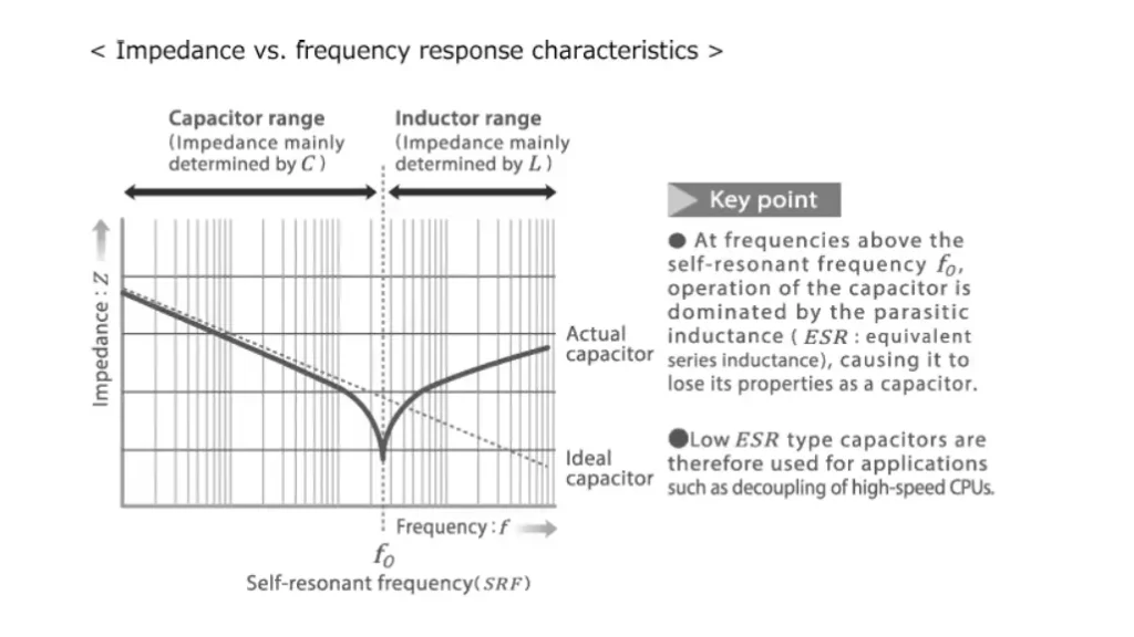
The resonant frequency of a ceramic capacitor is the frequency at which the capacitor’s inherent inductance and capacitance combine to form a resonant circuit.
This inherent inductance, also known as Equivalent Series Inductance (ESL), arises from the physical structure and internal connections of the capacitor. At the resonant frequency, the capacitive reactance and inductive reactance cancel each other out, resulting in a minimum impedance and a peak in the capacitor’s current.
Key Considerations:
- Operating Frequency: It’s crucial to operate ceramic capacitors below their resonant frequency. Above the resonant frequency, the capacitor’s behavior changes significantly, and it may start to exhibit inductive properties.
- Application: The resonant frequency is a critical parameter for high-frequency applications like RF circuits, where it directly impacts signal integrity and circuit performance.
- Capacitor Type: The resonant frequency varies depending on the type of ceramic capacitor, its size, and its construction.
By understanding the resonant frequency of ceramic capacitors, engineers can select the appropriate components for their specific applications and ensure optimal circuit performance.
What is the Frequency Range of Ceramic Capacitors
Ceramic capacitors exhibit a wide frequency range of operation, spanning from DC (direct current) to very high frequencies.
Low-Frequency Applications: They are effectively used in DC circuits and low-frequency AC applications, such as power supplies and audio circuits.
High-Frequency Applications: Many types of ceramic capacitors are specifically designed for high-frequency applications, including:
- RF Circuits: They are crucial components in radio frequency circuits, where they play a vital role in filtering, tuning, and impedance matching.
- Microwave Circuits: Certain ceramic capacitors are used in microwave circuits and other high-frequency systems due to their low parasitic inductance and high-frequency stability.
The specific frequency range of a particular ceramic capacitor depends on various factors, including its size, construction, and the dielectric material used.
What is the Resonant Frequency of MLCC
The resonant frequency of an MLCC (Multilayer Ceramic Capacitor) is the frequency at which its inherent inductance (ESL) and capacitance resonate.
The formula for calculating resonant frequency (f) is:
f = 1 / (2π√LC)
where:
- L is the Equivalent Series Inductance (ESL) of the MLCC
- C is the capacitance of the MLCC
This resonance phenomenon occurs due to the parasitic inductance present within the MLCC’s internal structure, such as the lead wires and internal electrode connections.
Key Considerations:
- Operating Frequency: It’s crucial to operate MLCCs below their resonant frequency. Above the resonant frequency, their impedance increases significantly, and they may exhibit inductive behavior, which can negatively impact circuit performance.
- Application: The resonant frequency is a critical parameter for high-frequency applications like RF circuits and microwave circuits, where it directly influences signal integrity and circuit stability.
- Temperature Stability: Temperature variations can affect the capacitance of the MLCC, which in turn can shift the resonant frequency. This is particularly important in applications where stable operation over a wide temperature range is required.
Understanding the resonant frequency of MLCCs is essential for proper circuit design and operation, especially in high-frequency applications. By carefully considering the MLCC’s characteristics and operating conditions, engineers can select the appropriate components and ensure optimal circuit performance.
How to Calculate Resonant Frequency
The resonant frequency of an LC circuit, which consists of an inductor (L) and a capacitor (C), is the frequency at which the inductive reactance (XL) and capacitive reactance (XC) are equal in magnitude.
- Inductive Reactance (XL): This is the opposition to the flow of alternating current (AC) caused by the inductor. It increases with frequency and is given by the formula:
- XL = 2πfL where:
- f is the frequency in Hertz (Hz)
- L is the inductance in Henrys (H)
- XL = 2πfL where:
- Capacitive Reactance (XC): This is the opposition to the flow of AC caused by the capacitor. It decreases with frequency and is given by the formula:
- XC = 1 / (2πfC) where:
- f is the frequency in Hertz (Hz)
- C is the capacitance in Farads (F)
- XC = 1 / (2πfC) where:
At resonance, XL = XC.
- Derivation of Resonant Frequency:
- 2πfL = 1 / (2πfC)
- f² = 1 / (4π²LC)
- f = 1 / (2π√LC)
Therefore, the resonant frequency (fr) of an LC circuit is given by:
- fr = 1 / (2π√LC)
This formula shows that the resonant frequency is inversely proportional to the square root of the product of inductance and capacitance.
Key Points:
- At resonance, the impedance of the LC circuit is at its minimum.
- The circuit exhibits maximum current flow at resonance.
- LC circuits are used in various applications, such as filters, oscillators, and tuning circuits.
How Do You Choose Resonant Frequency
The resonant frequency of an LC circuit is determined by the values of the inductance (L) and capacitance (C) within the circuit.
You can calculate the resonant frequency using the formula:
- f = 1 / (2π√(LC))
Where:
- f is the resonant frequency in Hertz (Hz)
- L is the inductance in Henrys (H)
- C is the capacitance in Farads (F)
This formula shows that the resonant frequency is inversely proportional to the square root of the product of inductance and capacitance.
Choosing the Resonant Frequency:
The choice of resonant frequency depends entirely on the specific application of the LC circuit. Some common applications and considerations include:
- Radio Frequency (RF) Circuits:
- In radio receivers and transmitters, the resonant frequency is chosen to select a specific radio station or band.
- This is often achieved by varying the capacitance in the circuit (e.g., using a variable capacitor) to tune the receiver to the desired frequency.
- Filters:
- LC circuits are used to filter out specific frequencies from a signal.
- The resonant frequency determines which frequencies are passed and which are blocked.
- Oscillators:
- LC circuits are essential components in electronic oscillators, which generate signals at a specific frequency.
- The resonant frequency of the LC circuit determines the frequency of the generated signal.
By carefully selecting the values of inductance and capacitance, engineers can design LC circuits with specific resonant frequencies to meet the requirements of various electronic systems.
How to Increase Resonant Frequency
To increase the resonant frequency of an LC circuit, you need to decrease either the inductance (L) or the capacitance (C), or both.
- Reducing Inductance:
- Use a smaller inductor with fewer turns of wire.
- Choose an inductor with a smaller core size or a different core material.
- Reducing Capacitance:
- Use a smaller capacitor with a lower capacitance value.
- Replace the existing capacitor with one that has a smaller physical size or a different dielectric material.
Key Point:
The resonant frequency (f) is inversely proportional to the square root of the product of inductance and capacitance (f = 1 / (2π√LC)). Therefore, decreasing either L or C will result in an increase in the resonant frequency.
Important Note:
- Adding another resistance in series or parallel with the existing components will generally not directly increase the resonant frequency.
- Decreasing the source frequency will move the system further away from resonance, not increase it.
What Affects Ceramic Capacitor Resonant Frequency
Several factors affect the resonant frequency of a ceramic capacitor:
- Capacitance Value: Higher capacitance values generally result in lower resonant frequencies.1 This is because the formula for resonant frequency (f = 1 / (2π√LC)) shows an inverse relationship between capacitance (C) and frequency (f).
- Equivalent Series Inductance (ESL): ESL arises from the physical structure of the capacitor, including the lead wires, internal electrodes, and the packaging.2 Lower ESL values lead to higher resonant frequencies.
- Capacitor Size and Geometry: Larger capacitors and those with more complex internal structures tend to have higher ESL and, therefore, lower resonant frequencies.
- Dielectric Material: The dielectric material used in the capacitor can influence its ESL and, consequently, its resonant frequency.
- Operating Temperature: Temperature variations can slightly affect the capacitance and ESL of the capacitor, which can in turn shift the resonant frequency.
By understanding these factors, engineers can select ceramic capacitors with appropriate resonant frequencies for their specific applications.
Conclusion
Understanding the resonant frequency of ceramic capacitors is crucial for optimizing circuit performance and avoiding unexpected behavior. By carefully considering the capacitor’s characteristics and the operating frequency of the circuit, designers can minimize losses, maximize efficiency, and ensure the stability of their electronic systems.
Whether you’re working on high-frequency applications like RF circuits or more general electronics, selecting the right ceramic capacitor is essential. Weishi, a leading electronic component manufacturer, offers a wide range of high-quality ceramic capacitors for various applications.
Ready to enhance your designs with top-tier ceramic capacitors? Contact Weishi today to explore our wholesale options and discover how our components can help you achieve your project goals.