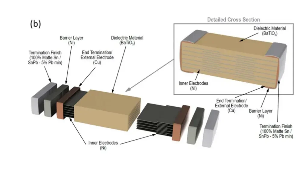
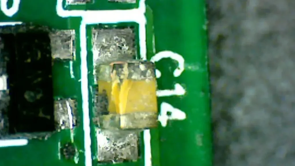
Ceramic capacitors are essential components in countless electronic devices, but they are not immune to failure. Understanding the common causes of failure can help engineers and technicians prevent these issues and ensure the reliability of their electronic systems.
Several factors can contribute to the failure of ceramic capacitors, including excessive voltage stress, temperature extremes, mechanical stress, aging, and manufacturing defects. By carefully considering these factors during design, selection, and operation, it is possible to significantly minimize the risk of capacitor failure and enhance the overall reliability of electronic systems.
What Is Ceramic Capacitor Failure
Ceramic capacitors can fail due to various factors, including dielectric breakdown, excessive leakage current, and degradation caused by environmental stresses.
Dielectric breakdown occurs when the voltage applied across the capacitor exceeds the strength of the insulating material, leading to a short circuit. Leakage current, while present in all capacitors, can increase significantly due to factors like high temperature, humidity, or aging, potentially causing component failure or affecting circuit performance.
Ceramic Capacitor Failure Modes

Ceramic capacitors can experience several failure modes, and let’s what causes a ceramic capacitor to fail?
- Dielectric Breakdown: This occurs when the voltage applied across the capacitor exceeds the strength of the insulating dielectric material. This can lead to a short circuit within the capacitor, permanently damaging the component.
- Excessive Leakage Current: Leakage current is the small current that flows through the dielectric material of the capacitor. While some leakage current is normal, excessive leakage can occur due to factors like high temperature, humidity, or aging. This can lead to increased power dissipation, overheating, and potential circuit malfunctions.
- Mechanical Failure: Physical stresses such as vibration, shock, and excessive pressure can cause ceramic capacitor crack failure or fractures in the ceramic body or the internal electrode layers, leading to open circuits or short circuits.
- Chemical Degradation: Exposure to harsh environments, such as high humidity or corrosive chemicals, can degrade the dielectric material or the electrode layers, leading to changes in capacitance, increased leakage current, and ultimately, failure.
- Aging: Over time, the properties of the dielectric material can degrade, leading to a gradual increase in leakage current, a decrease in capacitance, or an increase in equivalent series resistance (ESR).
| Failure Mode | Description | Potential Causes |
|---|---|---|
| Dielectric Breakdown | Breakdown of the insulating material | Excessive voltage, manufacturing defects |
| Excessive Leakage Current | Increased current flow through the dielectric | High temperature, humidity, aging, contamination |
| Mechanical Failure | Cracks, fractures, or delamination | Vibration, shock, excessive pressure, mishandling |
| Chemical Degradation | Degradation of the dielectric or electrodes | Exposure to harsh environments, corrosive chemicals |
| Aging | Gradual degradation of material properties | Time, temperature, operating conditions |
Understanding these failure modes helps in selecting appropriate capacitors for specific applications, implementing proper derating practices, and designing reliable electronic circuits.
Surface Mount Ceramic Capacitor Failure Modes

Surface Mount Ceramic Capacitors (SMCs) are prone to specific failure modes due to their small size and mounting method:
Cracking:
During Manufacturing: Cracks can form during the manufacturing process, such as during the sintering or dicing stages.
During Assembly:
- Soldering: Excessive heat or uneven cooling during reflow soldering can cause thermal stress, leading to cracks in the ceramic body.
- Mechanical Stress: Bending or flexing of the printed circuit board (PCB) can exert significant stress on the small SMCs, causing them to crack.
Delamination:
Separation between the internal electrode layers within the ceramic body can occur due to internal stresses, mechanical shock, or vibration.
Solder Joint Issues:
Poor Solder Joints: Insufficient solder volume, voids, or cold solder joints can lead to intermittent or complete loss of electrical contact.
Excessive Solder: Excess solder can cause short circuits between the capacitor leads or to adjacent components.
Dielectric Breakdown:
Similar to other ceramic capacitors, excessive voltage or electrical stress can cause dielectric breakdown, leading to a short circuit within the component.
| Failure Mode | Description | Potential Causes |
|---|---|---|
| Cracking | Fractures in the ceramic body | Manufacturing defects, thermal stress, mechanical stress |
| Delamination | Separation of internal electrode layers | Internal stresses, mechanical shock, vibration |
| Solder Joint Issues | Poor electrical contact | Insufficient solder, voids, cold solder joints, excessive solder |
| Dielectric Breakdown | Breakdown of the insulating material | Excessive voltage, electrical stress |
Mitigating Factors:
- Proper Soldering Techniques: Careful temperature control and appropriate solder paste selection are crucial to prevent thermal stress during reflow soldering.
- PCB Design: Avoid sharp bends and excessive stress on the PCB where SMCs are mounted.
- Component Selection: Choose SMCs with appropriate voltage and temperature ratings for the application.
- Quality Control: Implement rigorous quality control measures during manufacturing and assembly to minimize defects.
By understanding these failure modes and implementing appropriate preventative measures, it is possible to enhance the reliability and longevity of surface mount ceramic capacitors in electronic systems.
Ceramic Capacitor Crack Failure
Cracking is a significant failure mode for ceramic capacitors, particularly surface mount types. Cracks can form during manufacturing, such as during the sintering or dicing processes.
More commonly, cracks occur during assembly, primarily due to thermal stress during reflow soldering or mechanical stress caused by bending or flexing of the printed circuit board (PCB). These cracks can lead to electrical shorts, open circuits, or intermittent failures, impacting the reliability and performance of electronic systems.
High Voltage Ceramic Capacitor Failure
High voltage ceramic capacitors face unique failure challenges. Dielectric breakdown becomes a significant concern due to the high electric fields present. This can be exacerbated by factors like temperature variations, aging, and manufacturing defects within the dielectric material. Additionally, partial discharges, where localized breakdowns occur within the dielectric, can lead to gradual degradation and eventual failure.
It’s crucial to select high voltage ceramic capacitors with appropriate voltage ratings, consider derating factors, and implement robust design and manufacturing practices to minimize the risk of failure in these demanding applications.
Ceramic Capacitor Failure Short Circuit
A short circuit in a ceramic capacitor occurs when the insulating dielectric material between the electrodes breaks down. This allows current to flow directly between the terminals, bypassing the intended capacitance.
Short circuits can be caused by various factors, including:
* Overvoltage: Applying a voltage that exceeds the capacitor’s rated voltage can stress the dielectric material beyond its limits, leading to breakdown.
* Manufacturing Defects: Flaws in the manufacturing process, such as impurities in the dielectric material or imperfections in the electrode layers, can weaken the dielectric and increase the risk of short circuits.
* Mechanical Stress: Physical stress, such as excessive vibration, shock, or bending, can cause cracks in the ceramic body or delamination of the electrode layers, resulting in a short circuit path.
How to Tell if a Ceramic Capacitor is Bad
Several methods can help you determine if a ceramic capacitor is faulty.
Visual Inspection: Look for any physical signs of damage, such as cracks, bulges, or discoloration.
Multimeter Testing:
- Continuity Test: Set your multimeter to the diode or continuity mode. A good capacitor should show an initial low resistance reading followed by a gradual increase to a high resistance or an open circuit.
- Capacitance Measurement: If your multimeter has a capacitance measurement function, you can measure the capacitor’s value and compare it to the marked value. Significant deviations may indicate a faulty component.
In-Circuit Testing: If possible, test the capacitor within the circuit. Observe the circuit’s behavior and compare it to the expected operation. If the circuit malfunctions, the capacitor may be the culprit.
What Causes a Ceramic Capacitor to Burn?
Ceramic capacitors can burn due to excessive heat generation, typically caused by:
Overvoltage: Applying a voltage exceeding the capacitor’s rated voltage stresses the dielectric, leading to increased leakage current and excessive heat.
High Current: High current flow through the capacitor, often due to short circuits or other circuit faults, can generate significant heat.
Poor Solder Joints: Poor solder connections can increase resistance, leading to localized heating and potential component failure.
Internal Defects: Manufacturing defects within the capacitor, such as cracks or impurities in the dielectric, can increase internal resistance and contribute to heat generation.
Overcurrent Conditions: Transient overcurrent events, such as inrush currents or electrical surges, can generate excessive heat within the capacitor.
In all these cases, the generated heat can cause the capacitor to overheat, potentially leading to melting, smoking, or even catching fire.
How Do You Know if a Capacitor is Damaged?
You can often identify a damaged capacitor by visual inspection. Look for signs such as bulging, leaking, or discoloration. For a more thorough check, use a multimeter.
In resistance mode, a good capacitor will initially show low resistance, then gradually increase to a high resistance or open circuit. If your multimeter has a capacitance measurement function, compare the measured value to the marked value. Significant deviations may indicate a faulty component.
Keep in mind that these are basic checks. More sophisticated testing equipment like LCR meters offer more precise measurements.
Do Ceramic Capacitors Have Leakage Current?
Yes, ceramic capacitors, like all capacitors, exhibit some level of leakage current. Leakage current is a small current that flows through the dielectric material of the capacitor, even when no voltage is applied.
The amount of leakage current varies depending on factors such as the type of ceramic material, the capacitor’s construction, temperature, and age. While small amounts of leakage current are normal, excessive leakage can indicate a problem with the capacitor and can lead to issues like increased power dissipation, overheating, and potential circuit malfunctions.
Conclusion
In conclusion, understanding the factors that contribute to ceramic capacitor failure is crucial for ensuring the reliability and longevity of electronic systems. Common failure modes include dielectric breakdown, excessive leakage current, and degradation due to environmental factors such as temperature extremes and humidity.
To prevent premature failure, it is essential to select capacitors with appropriate voltage and current ratings, operate them within their specified temperature and humidity ranges, and implement proper derating practices. Careful consideration of these factors, along with proper circuit design and assembly techniques, can significantly enhance the reliability and lifespan of ceramic capacitors in your applications.
To learn more about ceramic capacitors and find the perfect components for your needs, we invite you to explore our extensive selection. For wholesale inquiries and competitive pricing on high-quality ceramic capacitors, please contact our sales team today.