This comprehensive guide will delve into the various symbols used to represent capacitors in electrical schematics. We’ll explore the common symbols for different types of capacitors, including ceramic capacitors, electrolytic capacitors, and more. Understanding these symbols is crucial for effectively interpreting and creating electrical circuit diagrams.
We’ll also discuss the historical evolution of capacitor symbols, their significance in circuit analysis, and how to correctly interpret and use them in your designs. Whether you’re a seasoned electrical engineer or a curious hobbyist, this guide will provide you with a solid foundation in capacitor symbology.
What is the Symbol for a Capacitor
The symbol for a capacitor in electrical schematics is typically represented by two parallel lines. These lines may be of equal length or one line may be slightly shorter, indicating the positive and negative terminals, although ceramic capacitors are non-polarized.
Sometimes, the symbol is depicted as a rectangle with one straight side and one curved or absent side. This variation helps distinguish it from other capacitor types in a circuit diagram.
Capacitor Symbol on Multimeter
What is the capacitor symbol on a multimeter?
The capacitor symbol on a multimeter typically resembles a stylized “F” or a simple graphical representation of a capacitor itself. This visual cue helps you easily identify the function for measuring capacitance.
The symbol might also be accompanied by the letter “C” or the unit “F” (for Farads), which is the unit of capacitance, to further clarify its purpose.
You’ll usually find this symbol on the dial or button of the multimeter. By rotating the dial or pressing the appropriate button to align with the capacitor symbol, you set the multimeter to measure capacitance values.
This symbol is crucial for correctly using your multimeter to test and measure capacitors in various electronic circuits.
Capacitor Symbol Types
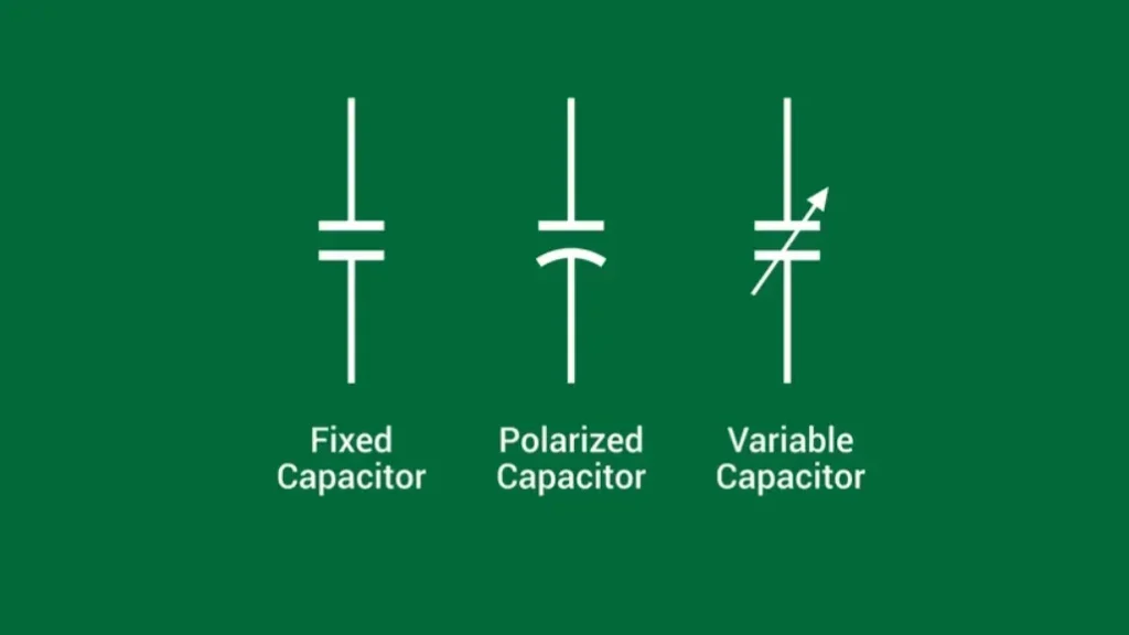
Capacitors, essential components in electronic circuits, are represented by various symbols in schematics. The most common symbol for a fixed (non-polarized) capacitor is two parallel lines of equal or slightly different lengths.
Polarized capacitors, such as electrolytic capacitors, are often depicted with a “+” sign on the positive terminal or a curved line representing the negative terminal.
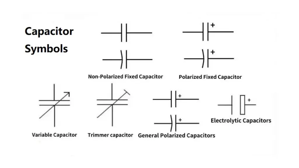
Other symbols include a rectangle with one straight side and one curved or absent side, and variations for specific types like variable capacitors (with an arrow indicating adjustability) and trimmer capacitors (with a diagonal line through the parallel lines).
Understanding these symbols is crucial for correctly interpreting circuit diagrams and effectively designing and troubleshooting electronic systems.
Here are some capacitor symbols with expanded explanations in the following:
1. Electrolytic Capacitor Symbol
- Symbol: Represented by two parallel lines, one straight and the other curved or absent. The curved line or absence of a line indicates the negative terminal. Sometimes, a “+” sign is marked on the positive terminal.
- Explanation: Electrolytic capacitors are polarized, meaning they have a specific positive and negative terminal. Connecting them with reverse polarity can cause damage. The symbol visually represents this polarity by differentiating between the two terminals. These capacitors are known for their high capacitance values in small packages and are widely used in power supply filtering and DC blocking.
2. Polarized Capacitor Symbol
- Symbol: Similar to the electrolytic capacitor symbol, with either a curved line on one terminal or a “+” sign on the positive terminal.
- Explanation: This symbol encompasses any capacitor that has a defined polarity. While electrolytic capacitors are the most common type, other polarized capacitors exist, such as tantalum capacitors. It’s crucial to observe the polarity markings to avoid damaging the component and the circuit.
3. Variable Capacitor Symbol
- Symbol: Two parallel lines with an arrow pointing between them.
- Explanation: Variable capacitors have a capacitance that can be adjusted. The arrow indicates the direction of adjustment, signifying that changing the position of a movable plate within the capacitor alters its capacitance. These are commonly used in radio tuners to adjust the frequency.
4. Non-Polarized Capacitor Symbol
- Symbol: Two parallel lines of equal length.
- Explanation: This is the most general symbol for capacitors. It represents capacitors that can be connected in any direction within a circuit without affecting their performance or causing damage. Ceramic disc capacitors, film capacitors, and mica capacitors are examples of non-polarized capacitors.
5. Ceramic Capacitor Symbol
- Symbol: Typically the same as the general non-polarized capacitor symbol (two parallel lines).
- Explanation: While there’s no specific symbol for ceramic capacitors, they are generally represented by the standard two-parallel-lines symbol. Ceramic capacitors are widely used due to their small size, high capacitance values, and good stability. They come in various types, including MLCCs (Multi-Layer Ceramic Capacitors) and disc capacitors.
6. Fixed Capacitor Symbol
- Symbol: Two parallel lines.
- Explanation: This symbol represents any capacitor with a fixed capacitance value that cannot be adjusted. This encompasses a wide range of capacitor types, including ceramic, film, mica, and electrolytic capacitors.
7. Bipolar Capacitor Symbol
- Symbol: Two parallel lines, sometimes with a small “B” or “BP” near the symbol.
- Explanation: Bipolar capacitors are a type of electrolytic capacitor designed to withstand reverse voltage. They can be connected in either direction without significant performance degradation, unlike standard electrolytic capacitors. The symbol may include a small “B” or “BP” to indicate its bipolar nature.
8. Coupling Capacitor Symbol
- Symbol: Two parallel lines, often used in circuit diagrams to specifically indicate a capacitor used for coupling signals between stages.
- Explanation: Although the symbol itself is the same as for other capacitors, the context within a circuit diagram often clarifies its role as a coupling capacitor. Coupling capacitors block DC signals while allowing AC signals to pass, enabling signal transfer between stages in amplifiers and other electronic circuits.
9. Film Capacitor Symbol
- Symbol: Typically the same as the general non-polarized capacitor symbol (two parallel lines).
- Explanation: Film capacitors use a thin film of dielectric material between two conductive layers. They are known for their low leakage current, high stability, and good temperature characteristics. While they don’t have a unique symbol, their specific characteristics are often noted in circuit diagrams or datasheets.
10. MFD Capacitor Symbol
- Symbol: Two parallel lines.
- Explanation: “MFD” stands for “microfarads,” a unit of capacitance. The symbol itself doesn’t specifically denote an “mfd capacitor.” Any capacitor with a capacitance value measured in microfarads can be represented by the standard two-parallel-lines symbol.
11. Mica Capacitor Symbol
- Symbol: Typically the same as the general non-polarized capacitor symbol (two parallel lines).
- Explanation: Mica capacitors use mica as the dielectric material. They are known for their excellent stability, low leakage current, and high Q factor. While they don’t have a unique symbol, their specific characteristics are often noted in circuit diagrams or datasheets.
12. Mylar Capacitor Symbol
- Symbol: Typically the same as the general non-polarized capacitor symbol (two parallel lines).
- Explanation: Mylar capacitors use Mylar film as the dielectric. They offer a good balance of performance and cost, making them suitable for various applications. While they don’t have a unique symbol, their specific characteristics are often noted in circuit diagrams or datasheets.
13. Polyester Capacitor Symbol
- Symbol: Typically the same as the general non-polarized capacitor symbol (two parallel lines).
- Explanation: Polyester capacitors use polyester film as the dielectric. They are known for their good temperature stability and self-healing properties. While they don’t have a unique symbol, their specific characteristics are often noted in circuit diagrams or datasheets.
14. Polypropylene Capacitor Symbol
- Symbol: Typically the same as the general non-polarized capacitor symbol (two parallel lines).
- Explanation: Polypropylene capacitors use polypropylene film as the dielectric. They are known for their low dielectric absorption, high stability, and excellent performance at high frequencies. While they don’t have a unique symbol, their specific characteristics are often noted in circuit diagrams or datasheets.
15. Tantalum Capacitor Symbol
- Symbol: Typically the same as the electrolytic capacitor symbol (two parallel lines, one straight and the other curved or absent).
- Explanation: Tantalum capacitors are polarized electrolytic capacitors known for their high capacitance density and small size.1 They use tantalum metal as the anode material.2 While they don’t have a unique symbol distinct from other electrolytic capacitors, their specific characteristics are often noted in circuit diagrams or datasheets.
Conclusion
In this guide, we’ve explored the various symbols used to represent capacitors in electrical schematics. Understanding these symbols is crucial for correctly interpreting circuit diagrams and effectively designing electronic systems. Whether you’re a seasoned engineer or a curious hobbyist, grasping the nuances of capacitor symbols will enhance your understanding of electronics.
We hope this guide has been informative and helpful. If you’re looking for high-quality capacitors for your projects, we invite you to explore our extensive inventory. We offer a wide range of capacitors, including ceramic disc capacitors, electrolytic capacitors, and more, at competitive wholesale prices.
Contact us today to discuss your specific requirements and discover how we can help you source the ideal capacitors for your projects. Let us be your trusted partner in all your electronic component needs.