Texas Instruments (TI)’s ULN2803ADWR is an eight-channel Darlington transistor array driver that provides reliable switching control for loads such as relays, solenoid valves, stepper motors, and small lighting systems.
Features such as open-collector output, high voltage withstand capability, built-in freewheeling diode, and integrated package, the ULN2803ADWR has become a classic output driver solution widely used in industrial control, home appliances, and electrical automation.
Product Overview
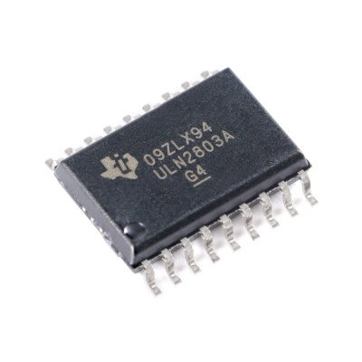
The ULN2803ADWR is part of the ULN2803A series, packaged in an SOIC-18 wide-body (DW) package and supplied in tape and reel (suffixed “R”), suitable for automated SMT production lines. This chip integrates eight NPN Darlington pairs, each with high current drive capability and inductive load protection, making it suitable for driving medium-power loads from logic controllers such as microcontrollers, PLCs, and FPGAs.
Each channel has the following key features:
- Up to 500 mA continuous collector output current;
- Can withstand load voltage up to 50 V;
- Input compatible with TTL and CMOS logic levels;
- Each channel has a built-in freewheeling diode to adapt to inductive loads;
- The common COM pin is connected to the freewheeling path, and GND is connected to the logic and power ground.
Core parameter characteristics
| Parameter | Specification |
| Number of channels | 8 |
| Output structure | Open-Collector NPN Darlington Pair |
| Maximum output current (single channel) | 500 mA |
| Maximum output voltage | 50 V |
| Input logic compatibility | TTL/CMOS |
| Built-in freewheeling diode | Yes (one per channel) |
| Power pin | No dedicated VCC pin required; COM pin connects to the freewheeling diode return path |
| Package Type | SOIC-18 DW (Wide Body SMD Package) |
| Thermal resistance RθJA | 66.4 °C/W (JEDEC PCB conditions) |
| Operating temperature range | –40°C to +85°C (industrial grade) |
Application advantages and engineering value
- Highly integrated multi-channel driving capability
Eight output channels support parallel control of multiple loads, significantly simplifying PCB design and control logic implementation. This makes it particularly suitable for applications such as multi-relay control boards, display driver boards, and buzzer/indicator arrays.
- Strong logical compatibility
The input is compatible with TTL/CMOS levels and can be directly driven by 3.3V/5V microcontrollers, FPGAs, and CNC systems, avoiding the need for additional level conversion devices.
- Inductive load protection capability
The flyback diodes integrated in each channel can safely drive inductive loads such as relays, solenoid valves, and DC motors, preventing reverse voltage from damaging the control device.
- No logic power supply required
The device itself does not require an additional VCC power supply. The inputs and outputs are based entirely on GND as a common reference, and the COM pin is connected to the positive voltage of the freewheeling path (e.g., 12V, 24V), which greatly simplifies the wiring and power supply structure.
Typical application scenarios
| Application | Description |
| Output stage of PLC or MCU control board | Acting as a driver bridge from low voltage logic to medium power loads |
| Multi-channel relay control board | Directly controls 8 12V/24V relay coils without external protection diodes |
| Light/Buzzer/Display Control | Suitable for multi-digit digital tube segment selection, buzzer control or LED indicator array |
| Solenoid valve group control | Parallel Control of Multi-channel Solenoid Valves in Industrial Pneumatic/Hydraulic Systems |
| Stepper Motor/Fan Array | Configure a channel for each winding or motor to achieve independent control and protection |
Comparison of products in the same series
The Darlington driver array product line, to which the ULN2803ADWR belongs, also includes models with different package types and channel counts. Below is a comparison of key parameters for several typical products to help engineers select the appropriate model based on system I/O resources and package requirements:
| Model | Number of Channels | Output Structure | Input Logic | Maximum Output Current | Package | Application Positioning |
| ULN2803ADWR | 8 | NPN open collector | TTL/CMOS | 500 mA | SOIC-18 Wide (SMD) | MCU/PLC drive, relay control |
| ULN2803APG | 8 | NPN open collector | TTL/CMOS | 500 mA | DIP-18 (through hole) | Educational platform, through-hole replacement design |
| ULN2803ADR | 7 | NPN open collector | TTL | 500 mA | SOIC-16 (SMD) | Stepper motor control, relay group drive (saving PCB space) |
Note: All models listed above are members of the ULN series, with slight differences in the number of channels, package size, and input levels, and are suitable for system designs with varying cost and space constraints.
PCB Design Recommendations
- Input current limiting resistor: For long-distance transmission or in situations with strong electromagnetic interference, it is recommended to connect a current-limiting resistor of about 1 kΩ in series at the input to enhance the signal’s anti-interference capability; in normal short-circuit applications, this is not necessary.
- Freewheeling path design: Ensure that the COM pin is connected to the positive terminal of the load power supply to form a freewheeling path, in order to prevent induced voltage spikes from damaging the output;
- Ground design: GND should be the common ground for logic circuits and power supply. During layout, ensure unobstructed loops and avoid high-current ground loops.
- Heat dissipation assessment: When the total output current exceeds 300–400 mA, be aware of the increased junction temperature, with a corresponding thermal conductivity of RθJA (66.4 °C/W). Appropriate copper foil or grounding blocks should be provided to aid in heat dissipation.
- Mixed-voltage design note: When using the ULN2803ADWR to drive high-voltage (e.g., 24V) loads, ensure that there is sufficient creepage distance between the logic terminals and the output area.