Capacitors are essential components in the world of electronics, serving as the backbone for energy storage, filtering, and signal processing in countless devices we use every day. While the parallel plate capacitor is often the go-to example in textbooks, there’s a whole spectrum of capacitor configurations that offer unique insights and applications. One such fascinating variation is the spherical capacitor.
A spherical capacitor consists of two concentric spherical conducting shells, separated by an insulating material or vacuum. This configuration not only provides a richer understanding of electrostatic principles but also finds relevance in advanced technological applications, such as in certain types of sensors and energy storage systems.
In this blog post, we’ll delve into what a spherical capacitor is and unravel the physics behind how it works. Whether you’re an electronics enthusiast, a student gearing up for exams, or just curious about the intricacies of electric fields and potential, this exploration will shed light on the elegant symmetry and functionality of spherical capacitors. Let’s embark on this journey to understand how a simple shape can reveal complex electrical properties and contribute to the technological advancements of our time.
What Is a Spherical Capacitor
A spherical capacitor is an electrical component that consists of two concentric spherical conducting shells separated by a dielectric material.
A spherical capacitor consists of two concentric spherical conductors. True
A spherical capacitor is a type of capacitor that consists of two concentric spherical conductors. The inner sphere is typically smaller and carries a positive charge, while the outer sphere is larger and carries an equal and opposite negative charge. The space between the two spheres is filled with a dielectric material, which increases the capacitance of the device.
Spherical capacitors have uniform electric field between the plates. False
While a parallel plate capacitor, under ideal conditions, has a nearly uniform electric field between its plates, a spherical capacitor does not. The electric field in a spherical capacitor is not uniform and varies with the distance from the center of the spheres. It is stronger closer to the inner sphere and weaker closer to the outer sphere.
Spherical Capacitor Structure
Structure:
- Inner Shell: A solid or hollow sphere of conducting material.
- Outer Shell: A larger, concentric spherical shell that encloses the inner shell.
- Dielectric: An insulating material (like air, glass, or ceramic) fills the space between the two shells.
What is Spherical Capacitor Used For
While not as common as other capacitor types like parallel-plate capacitors, spherical capacitors find applications in a few specific areas:
High-Voltage Applications:
Their spherical geometry helps to minimize the risk of electrical breakdown at high voltages. The curvature of the surfaces helps to distribute the electric field more evenly, reducing the likelihood of localized high-field regions where breakdown is more likely to occur.1
Electrostatic Experiments:
Spherical capacitors are often used in laboratory setups to study electrostatic phenomena and demonstrate fundamental principles of electrostatics, such as Gauss’s Law and the concept of capacitance.
Specialized Research:
They may be used in specific research areas where their unique geometry or electrical properties are advantageous for particular experimental setups.
It’s important to note:
- Spherical capacitors are not as widely used in everyday electronics compared to other capacitor types due to their more complex construction and potential manufacturing challenges.
- Parallel-plate capacitors are generally more practical and easier to manufacture for most applications.
Spherical Capacitor Formula
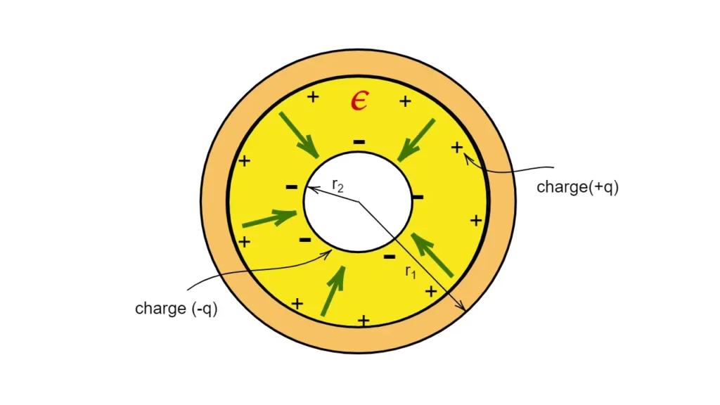
A spherical capacitor is a fundamental electrical component consisting of two concentric spherical conducting shells. The inner shell has a radius r<sub>1</sub>, and the outer shell has a radius r<sub>2</sub>.
Key Concepts
- Charge Distribution: When a charge +Q is placed on the inner sphere and -Q on the outer sphere, the charge distribution on each sphere is uniform due to symmetry.
- Electric Field:
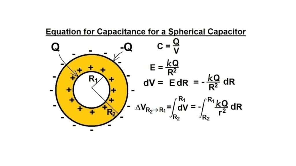
- The electric field between the spheres can be determined using Gauss’s Law.
- At a distance r from the center (where r<sub>1</sub> < r < r<sub>2</sub>), the electric field is given by: E = Q / (4πε₀r²)
- This shows that the electric field is not uniform and varies inversely with the square of the distance from the center.
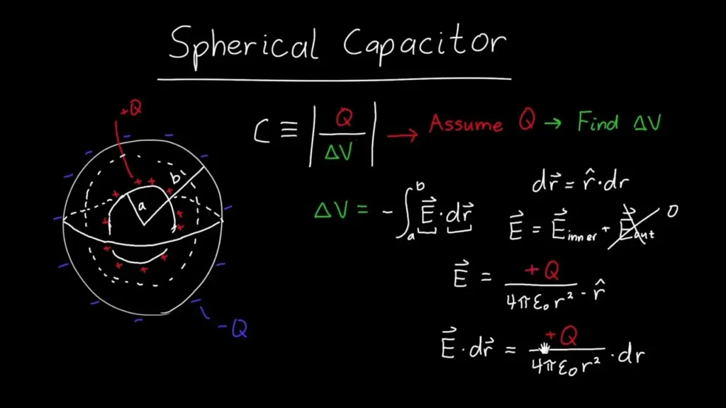
- Potential Difference:
- The potential difference (V) between the spheres is found by integrating the electric field: V = – ∫ E dr V = – ∫ (Q / 4πε₀r²) dr (from r<sub>2</sub> to r<sub>1</sub>) V = (Q / 4πε₀) * (1/r<sub>1</sub> – 1/r<sub>2</sub>)
Capacitance Formula
The capacitance (C) of a spherical capacitor is defined as the ratio of charge (Q) to the potential difference (V):
C = Q / V
Substituting the expression for V, we get:
C = Q / [(Q / 4πε₀) * (1/r<sub>1</sub> – 1/r<sub>2</sub>)]
C = 4πε₀ / (1/r<sub>1</sub> – 1/r<sub>2</sub>)
Finally, simplifying the equation leads to the capacitance formula:
C = 4πε₀ * (r<sub>1</sub> * r<sub>2</sub>) / (r<sub>2</sub> – r<sub>1</sub>)
where:
- ε₀ is the permittivity of free space
- r<sub>1</sub> is the radius of the inner sphere
- r<sub>2</sub> is the radius of the outer sphere
Key Points
- The capacitance of a spherical capacitor depends on the radii of both spheres.
- As the distance between the spheres decreases (r<sub>2</sub> – r<sub>1</sub> becomes smaller), the capacitance increases.
- The presence of a dielectric material between the spheres increases the capacitance.
Applications
Spherical capacitors, while less common than parallel-plate capacitors, find applications in specialized areas such as:
- High-voltage applications: Their spherical geometry helps to minimize the risk of electrical breakdown.
- Electrostatic experiments: They are used in laboratory setups to study electrostatic phenomena.
Sum up
The spherical capacitor formula provides a fundamental understanding of how the capacitance of this specific geometry is related to its dimensions and the properties of the surrounding medium. This knowledge is crucial in various fields of physics and engineering.
Spherical Capacitor Capacitance Formula
The capacitance of a spherical capacitor is given by:
C = 4πε₀ * (r₁ * r₂) / (r₂ – r₁)
Where:
- C is the capacitance of the spherical capacitor
- ε₀ is the permittivity of free space (approximately 8.85 x 10⁻¹² F/m)
- r₁ is the radius of the inner sphere
- r₂ is the radius of the outer sphere
This formula shows that the capacitance of a spherical capacitor depends on:
- The radii of both spheres: As the difference between the radii (r₂ – r₁) decreases, the capacitance increases.
- The permittivity of the medium: If a dielectric material is placed between the spheres, the capacitance will increase.
This formula is derived using Gauss’s Law and by calculating the electric field and potential difference between the spheres.
Spherical Capacitor Formula Derivation
1. Charge Distribution
- Assume a charge +Q is placed on the inner sphere and -Q on the outer sphere.
- Due to symmetry, the charge distribution on each sphere will be uniform.
2. Electric Field
- Apply Gauss’s Law:
- Consider a spherical Gaussian surface with radius r (where r<sub>1</sub> < r < r<sub>2</sub>) centered at the common center of the spheres.
- Gauss’s Law states that the electric flux through a closed surface is proportional to the charge enclosed within that surface: Φ<sub>E</sub>1 = ∫ E ⋅ dA = Q<sub>enclosed</sub> / ε₀
- Since the electric field (E) is radial and the surface area of the Gaussian sphere is 4πr², the equation simplifies to: E * 4πr² = Q<sub>enclosed</sub> / ε₀
- The charge enclosed within the Gaussian surface is simply the charge on the inner sphere: Q<sub>enclosed</sub> = Q
- Therefore, the electric field between the spheres is: E = Q / (4πε₀r²)
3. Potential Difference
- Calculate the potential difference (V) between the spheres:
- The potential difference is the work done per unit charge to move a test charge from the outer sphere to the inner sphere.
- V = – ∫ E dr (from r<sub>2</sub> to r<sub>1</sub>)
- V = – ∫ (Q / 4πε₀r²) dr (from r<sub>2</sub> to r<sub>1</sub>)
- V = (Q / 4πε₀) * (1/r<sub>1</sub> – 1/r<sub>2</sub>)
4. Capacitance
- By definition, capacitance (C) is the ratio of charge (Q) to potential difference (V):
- C = Q / V
- C = Q / [(Q / 4πε₀) * (1/r<sub>1</sub> – 1/r<sub>2</sub>)]
- C = 4πε₀ / (1/r<sub>1</sub> – 1/r<sub>2</sub>)
- C = 4πε₀ * (r<sub>1</sub> * r<sub>2</sub>) / (r<sub>2</sub> – r<sub>1</sub>)
Therefore, the capacitance of a spherical capacitor is given by:
C = 4πε₀ * (r<sub>1</sub> * r<sub>2</sub>) / (r<sub>2</sub> – r<sub>1</sub>)
where:
- ε₀ is the permittivity of free space
- r<sub>1</sub> is the radius of the inner sphere
- r<sub>2</sub> is the radius of the outer sphere
Key Points
- The electric field between the spheres of a spherical capacitor is not uniform.11
- The capacitance of a spherical capacitor depends on the radii of both spheres.
- As the distance between the spheres decreases (r<sub>2</sub> – r<sub>1</sub> becomes smaller), the capacitance increases.
This derivation provides a fundamental understanding of the capacitance of a spherical capacitor and its dependence on the geometry of the system.
Spherical Capacitor With Dielectric
When a dielectric material is inserted between the concentric spheres of a spherical capacitor, it significantly increases the capacitance.
Here’s how:
1. Effect of Dielectric
- Reduced Electric Field:
- The dielectric material, with its own bound charges, weakens the electric field between the spheres.
- This reduction in the electric field is characterized by the dielectric constant (κ), a dimensionless quantity that describes the material’s ability to reduce the electric field.
- Increased Capacitance:
- Since the potential difference (V) across the capacitor is directly related to the electric field (V = -∫ E dr), a weaker electric field results in a lower potential difference for the same charge.
- As capacitance (C) is defined as C = Q/V, a lower potential difference for the same charge leads to an increase in capacitance.
2. Capacitance Formula
The capacitance of a spherical capacitor with a dielectric material filling the space between the spheres is given by:
C = 4πε₀κ * (r₁ * r₂) / (r₂ – r₁)
where:
- ε₀ is the permittivity of free space
- κ is the dielectric constant of the material
- r₁ is the radius of the inner sphere
- r₂ is the radius of the outer sphere
Key Points
- The presence of a dielectric material significantly increases the capacitance of a spherical capacitor.
- The dielectric constant (κ) of the material determines the extent of this increase.
- Higher dielectric constants lead to higher capacitance values.
Applications
- Increased Capacitance in Smaller Volumes: Using a dielectric allows for the creation of capacitors with higher capacitance values while maintaining the same physical dimensions.
- Improved Voltage Handling: Dielectric materials can increase the breakdown voltage of the capacitor, making it suitable for higher voltage applications.
Spherical Capacitor Electric Field
Electric Field in a Spherical Capacitor
Configuration:
- A spherical capacitor consists of two concentric conducting spherical shells.
- The inner sphere has a radius r<sub>1</sub>.
- The outer sphere has a radius r<sub>2</sub>.
- Charge +Q is placed on the inner sphere, and -Q is placed on the outer sphere.
Determining the Electric Field:
Apply Gauss’s Law:
- We use a spherical Gaussian surface with radius r (where r<sub>1</sub> < r < r<sub>2</sub>) centered at the common center of the spheres.
- Gauss’s Law states: ΦE = ∫ E ⋅ dA = Qenclosed / ε₀
- Φ<sub>E</sub> is the electric flux
- E is the electric field
- dA is the differential area vector
- Q<sub>enclosed</sub> is the charge enclosed within the Gaussian surface
- ε₀ is the permittivity of free space
Simplification:
Since the electric field (E) is radial and the surface area of the Gaussian sphere is 4πr², the equation simplifies to: E * 4πr² = Q<sub>enclosed</sub> / ε₀
Charge Enclosed:
The charge enclosed within the Gaussian surface is simply the charge on the inner sphere: Q<sub>enclosed</sub> = Q
Electric Field:
Therefore, the electric field between the spheres is: E = Q / (4πε₀r²)
Key Characteristics:
The electric field between the spheres is not uniform.
It varies inversely with the square of the distance (r) from the center.
The field is stronger closer to the inner sphere and weaker closer to the outer sphere.
The electric field in a spherical capacitor decreases radially with distance from the center, distinguishing it from the uniform electric field of an ideal parallel-plate capacitor.
Spherical Capacitor Problems
Spherical capacitors are composed of two concentric conducting spheres. Here are some common problems and how to approach them:
1. Finding Capacitance
- Given: Inner radius (a), outer radius (b)
- Approach:
- Use Gauss’s Law to find the electric field between the spheres.
- Calculate the potential difference between the spheres by integrating the electric field.
- Use the definition of capacitance: C = Q/V, where Q is the charge on the inner sphere and V is the potential difference.
2. Finding Charge or Potential Difference
- Given: Capacitance (C), one of the above (Q or V)
- Approach:
- Use the capacitance formula: Q = CV or V = Q/C
3. Finding Energy Stored
- Given: Capacitance (C), potential difference (V), or charge (Q)
- Approach:
- Use one of the following energy formulas:
- U = (1/2)CV^2
- U = (1/2)QV
- U = (1/2)Q^2/C
- Use one of the following energy formulas:
4. Effect of Dielectric
- Given: Capacitance in air (C₀), dielectric constant (κ)
- Approach:
- The capacitance with the dielectric is: C = κC₀
Example Problem
A spherical capacitor has an inner radius of 5 cm and an outer radius of 10 cm.
- Find the capacitance.
Solution
Find the electric field:
- Use Gauss’s Law to find the electric field between the spheres. Due to spherical symmetry, the electric field will be radial and depend only on the distance from the center.
- E = kQ/r² where k is Coulomb’s constant, Q is the charge on the inner sphere, and r is the distance from the center.
Find the potential difference:
- Integrate the electric field from the inner radius (a) to the outer radius (b):
- V = -∫(kQ/r²) dr from a to b
- V = kQ (1/a – 1/b)
Find the capacitance:
- C = Q/V
- C = 1 / (k * (1/a – 1/b))
- Substitute the values of a and b to find the capacitance.
Key Considerations
- Assumptions: These calculations assume that the spheres are perfect conductors and that the space between them is filled with a uniform dielectric.
- Units: Ensure consistent units throughout the calculations (e.g., meters for radii, Farads for capacitance).
Conclusion
In wrapping up, spherical capacitors provide a unique perspective on how geometry affects electrical properties. Their design allows for uniform electric fields and optimal capacitance in a compact form, making them essential in specialized applications. Understanding their operation not only deepens your grasp of electrostatics but also enhances your ability to innovate in the field of electronics.
If you’re seeking high-quality capacitors at wholesale prices, we’re here to help. Contact us today to explore our extensive range of capacitors and find the perfect components for your projects.