Capacitors, those often overlooked components, play a vital role in the heart of every electronic circuit. When mounted on a Printed Circuit Board (PCB), these tiny components become the unsung heroes, ensuring the smooth and efficient operation of countless devices.
In this comprehensive guide, we’ll delve into the world of PCB capacitors, exploring their types, functions, and how to select the right ones for your specific needs. We’ll cover everything from understanding their basic principles to mastering advanced applications.
So, whether you’re a seasoned electronics engineer or a curious hobbyist, join us on this journey to uncover the secrets of PCB capacitors.
What Is PCB Capacitor
A PCB capacitor is a vital component in electronic circuits, acting as a temporary energy storage device. It consists of two conductive plates separated by a dielectric material. When voltage is applied, electrical charge accumulates on the plates, creating an electric field.
PCB Capacitor Types
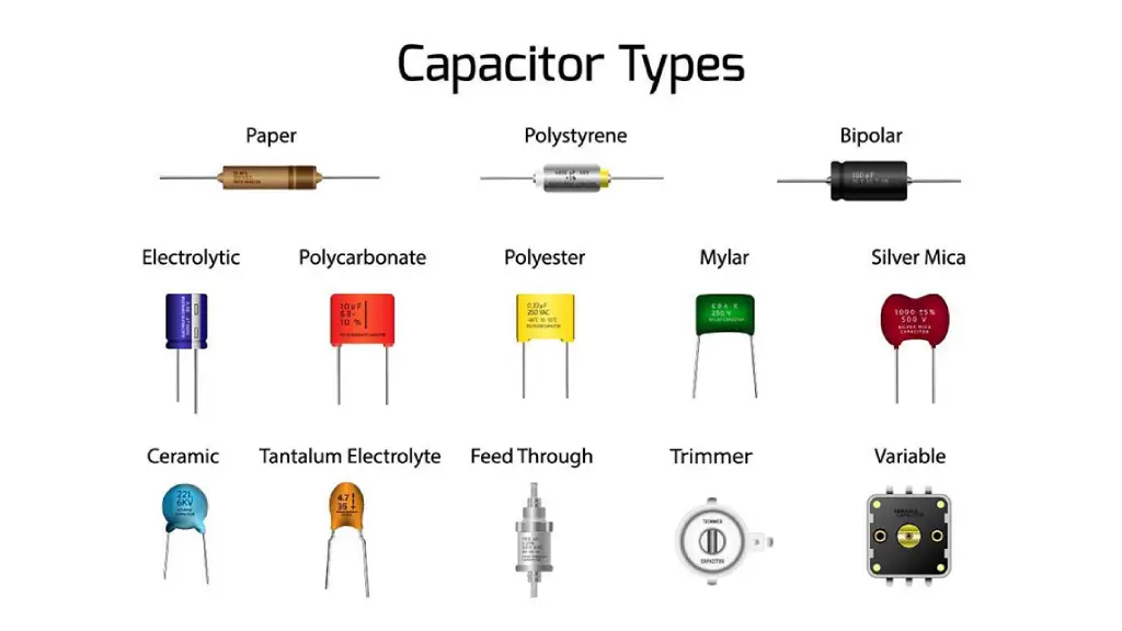
PCB capacitors are essential components in electronic circuits, playing a crucial role in filtering, coupling, timing, and energy storage. Different types of capacitors are used based on specific circuit requirements. Here’s a deeper look into some common types:
Ceramic Capacitors
- Multilayer Ceramic Capacitors (MLCCs): These are the most common type, offering high capacitance in a small package. They’re widely used for decoupling, bypassing, and filtering.
- Ceramic Disc Capacitors: These are typically used for high-frequency applications, such as coupling and bypassing.
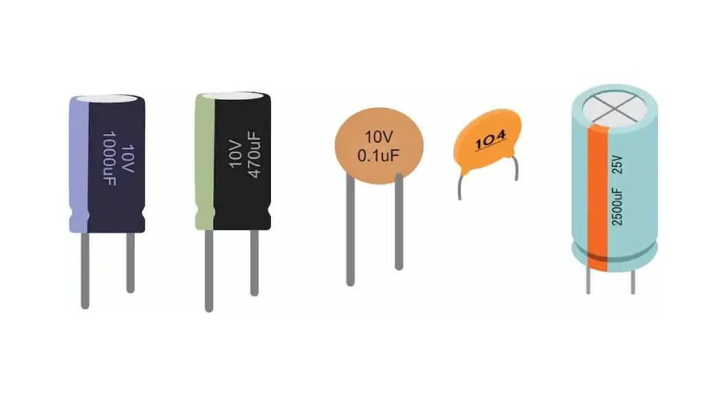
Electrolytic Capacitors
- Aluminum Electrolytic Capacitors: These offer high capacitance values in a relatively small package. They’re commonly used for power supply filtering and energy storage.
- Tantalum Electrolytic Capacitors: Known for their low leakage current and high stability, they are often used in timing circuits and power supply filtering.
- Polymer Capacitors: These offer low ESR (Equivalent Series Resistance) and high ripple current handling capabilities, making them suitable for high-frequency applications and power supply filtering.
Film Capacitors
- Polyester Film Capacitors: These are known for their stability and reliability, making them suitable for a wide range of applications, including audio circuits, timing circuits, and power supply filtering.
- Polypropylene Film Capacitors: These offer low ESR and high-frequency performance, making them ideal for high-frequency filters and timing circuits.
- Metallized Film Capacitors: These offer high capacitance values in a small package, making them suitable for power supply filtering and motor control applications.
Other Types
- Ceramic Disc Capacitors: Used for high-frequency applications, such as coupling and bypassing.
- Variable Capacitors: Used for tuning circuits, such as those in radios and TVs.
- Supercapacitors: High-capacity capacitors used for energy storage in devices like electric vehicles and renewable energy systems.
Key Considerations for Capacitor Selection:
- Capacitance Value: The required capacitance value depends on the specific application.
- Voltage Rating: The capacitor must be rated for the maximum voltage that will be applied across it.
- Tolerance: The tolerance specifies the allowable deviation from the marked capacitance value.14
- Temperature Range: The capacitor should be able to operate within the temperature range of the circuit.
- ESR (Equivalent Series Resistance): Lower ESR is desirable for high-frequency applications.15
- Package Size and Mounting Style: The capacitor should be physically compatible with the PCB layout.
By understanding the different types of PCB capacitors and their characteristics, you can make informed decisions when designing and building electronic circuits.
Decoupling Capacitor PCB Layout
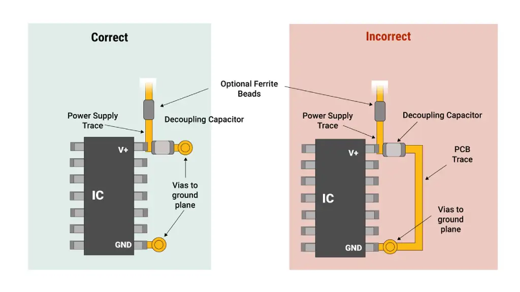
Decoupling capacitors are essential components in electronic circuit design to stabilize power supply voltages and reduce noise. Proper decoupling capacitor placement PCB and routing are crucial for optimal performance.
Key Considerations for Decoupling Capacitor Placement:
- Proximity to the Power Pin:
- Place the decoupling capacitor as close as possible to the power pin of the integrated circuit (IC) it’s intended to decouple. This minimizes the inductance of the power supply path, reducing noise and improving stability.
- Direct Connection:
- Connect the capacitor directly to the power and ground pins of the IC, avoiding long traces.
- Use short, wide traces to minimize inductance and resistance.
- Ground Plane:
- Place the decoupling capacitor close to a ground plane to reduce noise and improve signal integrity.
- Multiple Decoupling Capacitors:
- For complex circuits with multiple ICs, use multiple decoupling capacitors of different values to effectively filter out a wide range of noise frequencies.
- Capacitor Values and Types:
- Use a combination of ceramic capacitors for high-frequency noise and electrolytic capacitors for low-frequency noise.
- The specific values of the capacitors will depend on the circuit’s requirements and the frequency range of the noise to be filtered.
Best Practices for Decoupling Capacitor Routing:
- Short, Direct Traces: Keep the traces connecting the capacitor to the IC as short and direct as possible to minimize inductance.
- Wide Traces: Use wide traces to reduce resistance and improve current handling capability.
- Avoid Right-Angle Bends: Right-angle bends can introduce inductance, so use 45-degree angles instead.
- Ground Plane Connections: Connect the ground side of the capacitor directly to a ground plane to reduce noise and improve stability.
By following these guidelines, you can effectively decouple your circuit, improve its performance, and reduce the risk of noise-related issues.
Capacitor Polarity on PCB
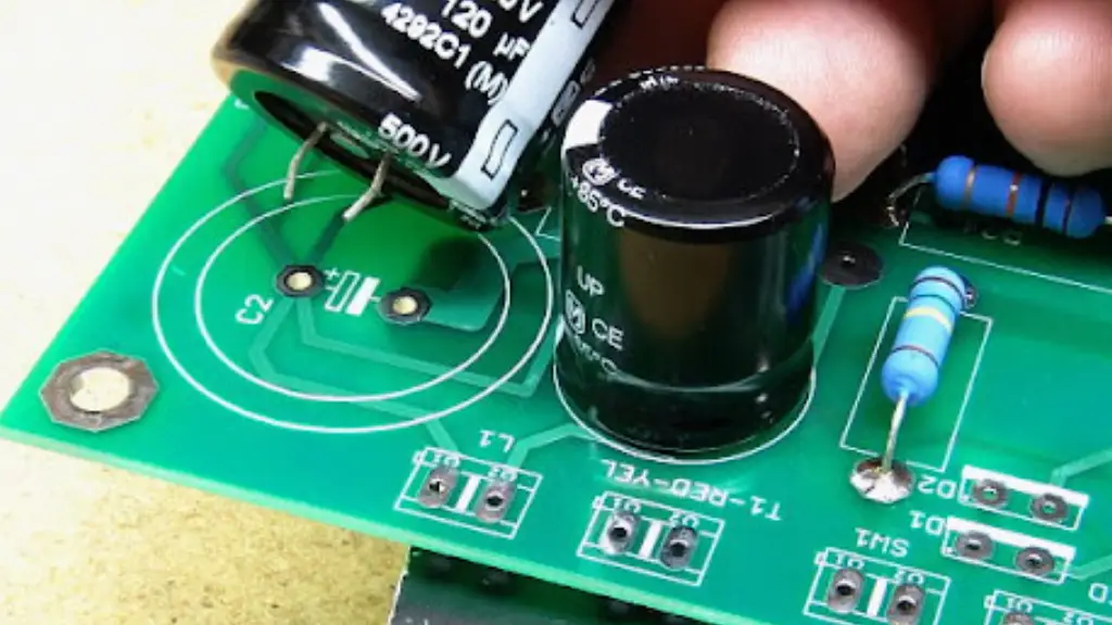
Polarized Capacitors
Polarized capacitors, such as electrolytic and tantalum capacitors, require specific polarity to function correctly. Incorrect polarity can lead to damage or even explosion.
Identifying Polarity:
Physical Markings:
- Plus (+) and Minus (-) Signs: These are the most common markings. The positive terminal is usually longer than the negative one.
- Color Coding: Some capacitors use color bands to indicate polarity. Consult the manufacturer‘s datasheet for specific color codes.
PCB Layout:
- Pad Size and Shape: The positive terminal pad may be larger or have a different shape than the negative terminal pad.
- Silkscreen Markings: The PCB silkscreen may have markings indicating polarity, such as “+” and “-” signs or arrows.
Important Considerations:
- Always check the datasheet: Refer to the manufacturer‘s datasheet for specific polarity information.
- Double-check the PCB layout: Ensure that the capacitor is oriented correctly on the PCB.
- Use a multimeter: You can use a multimeter to verify the polarity of a capacitor, but be cautious not to exceed the voltage rating.
Non-polarized capacitors, such as ceramic and film capacitors, do not have polarity and can be installed in any orientation. They are commonly used for coupling, filtering, and timing applications.
By carefully following these guidelines, you can ensure that your capacitors are correctly installed and your electronic circuits function reliably.
If you have any specific questions about a particular capacitor or PCB layout, feel free to provide more details.
Capacitor PCB Marking
Capacitors, essential components in electronic circuits, often have markings that provide crucial information about their specifications.1 These markings can vary depending on the capacitor type and manufacturer, but they typically convey details such as:
Capacitance Value
Numeric Code:
- Two-Digit Code: Directly indicates the capacitance value in picofarads (pF). For example, “47” means 47 pF.
- Three-Digit Code: The first two digits represent the significant figures, and the third digit indicates the number of zeros. For example, “224” means 22 x 10^4 pF = 220,000 pF = 0.22 µF.2
Capacitor Tolerance
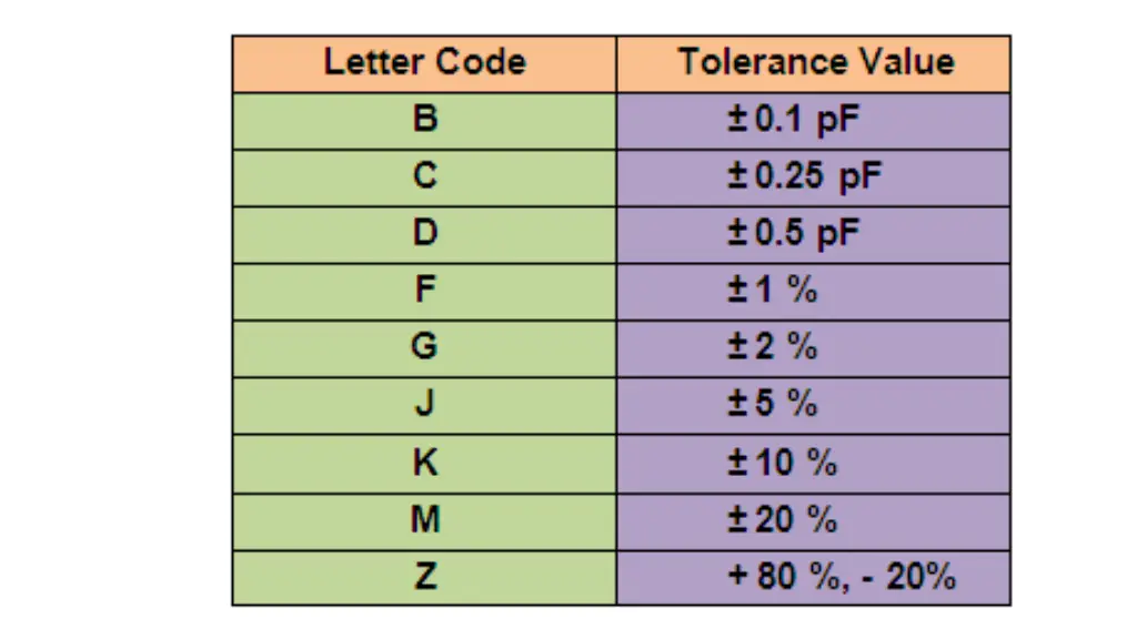
The tolerance code indicates the permissible deviation of the actual capacitance from the marked value. Common tolerance codes include:
- B: ± 0.1%
- C: ± 0.25%3
- D: ± 0.5%4
- F: ± 1%
- G: ± 2%
- J: ± 5%
- K: ± 10%5
- M: ± 20%
Voltage Rating
The voltage rating indicates the maximum voltage that can be applied across the capacitor without damaging it.6 It’s often abbreviated as “V” or “VDC.”
Temperature Range
The temperature range specifies the operating temperature limits within which the capacitor can function reliably.
Other Markings
- Manufacturer‘s Code: A unique code identifying the manufacturer.
- Date Code: A code indicating the manufacturing date.
- Polarity Indication: For polarized capacitors (like electrolytic capacitors), a “+” sign indicates the positive terminal.7
Example:
A capacitor marked as “224J 100V” would have:
- Capacitance: 220,000 pF or 0.22 µF
- Tolerance: ±5%
- Voltage Rating: 100V
Additional Tips for Reading Capacitor Markings:
- Refer to the Manufacturer‘s Datasheet: For specific details and interpretations, consult the datasheet provided by the manufacturer.
- Use Online Tools: There are online tools and resources that can help decode capacitor markings.
- Consult with Electronics Experts: If you encounter complex or ambiguous markings, seek advice from experienced electronics professionals.
By understanding capacitor markings, you can accurately identify and select the right components for your electronic projects.
PCB Capacitor Identification
Identifying PCB capacitors involves deciphering the markings printed on their surface.1 These markings typically convey information about the capacitor’s capacitance, voltage rating, tolerance, and sometimes the manufacturer‘s code.
Here’s a breakdown of how to interpret these markings:
Capacitance Value:
Numeric Code:
- Two-Digit Code: Directly indicates the capacitance value in picofarads (pF). For example, “47” means 47 pF.
- Three-Digit Code: The first two digits represent the significant figures, and the third digit indicates the number of zeros. For example, “224” means 22 x 10^4 pF = 220,000 pF = 0.22 µF.2
Capacitor Tolerance:
The tolerance code indicates the permissible deviation of the actual capacitance from the marked value. Common tolerance codes include:
- B: ± 0.1%
- C: ± 0.25%3
- D: ± 0.5%
- F: ± 1%
- G: ± 2%
- J: ± 5%
- K: ± 10%4
- M: ± 20%5
Voltage Rating:
The voltage rating indicates the maximum voltage that can be applied across the capacitor without damaging it.6 It’s often abbreviated as “V” or “VDC.”
Manufacturer’s Code:
This code identifies the manufacturer of the capacitor.
Example: A capacitor marked as “224J 100V” would have:
- Capacitance: 220,000 pF or 0.22 µF
- Tolerance: ±5%
- Voltage Rating: 100V
Additional Tips:
- Refer to the Manufacturer‘s Datasheet: For specific details and interpretations, consult the datasheet provided by the manufacturer.
- Use Online Tools: There are online tools and resources that can help decode capacitor markings.7
- Consult with Electronics Experts: If you encounter complex or ambiguous markings, seek advice from experienced electronics professionals.
By understanding these markings, you can accurately identify and select the right capacitors for your electronic projects.
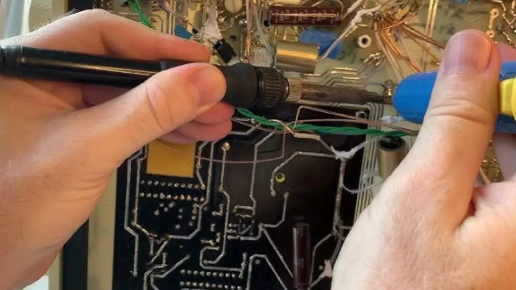
PCB Capacitor Disposal
Polychlorinated biphenyl (PCB) capacitors are a specific type of capacitor that contains polychlorinated biphenyls, a hazardous substance. Due to their potential environmental and health risks, the disposal of PCB capacitors is strictly regulated.
Here’s how to properly dispose of PCB capacitors:
Identification:
- Labeling: Look for labels indicating the presence of PCBs.
- Visual Inspection: Some older capacitors, especially those with a dark, oily fluid inside, may contain PCBs.
Consult Local Regulations:
- EPA Guidelines: In the US, the Environmental Protection Agency (EPA) has specific regulations for PCB disposal.
- Local Regulations: Check with your local environmental agency for specific guidelines and regulations.
Professional Disposal:
- Certified Companies: Contact a certified waste disposal company that specializes in hazardous materials.
- Proper Handling: These companies have the expertise and equipment to handle PCB capacitors safely and legally.
Important Considerations:
- Do Not Attempt DIY Disposal: Improper disposal of PCB capacitors can lead to environmental contamination and health risks.
- Storage: Store PCB capacitors in a secure, dry location, away from heat and direct sunlight.4
- Labeling: Clearly label containers containing PCB capacitors to avoid accidental disposal.5
By following these guidelines and working with certified professionals, you can ensure the safe and environmentally responsible disposal of PCB capacitors.
Please note: Specific regulations and disposal procedures may vary depending on your location. Always consult with local authorities and environmental agencies for the most accurate information.
Conclusion
PCB capacitors are essential components that significantly impact the performance and reliability of electronic circuits. By understanding their types, functions, and selection criteria, you can optimize your designs.
Elevate Your Designs with Premium Capacitors
Ready to source high-quality PCB capacitors for your projects? We offer a wide range of capacitors, tailored to meet the diverse needs of electronic designers.
Choose our electronic component manufacturer for reliable, efficient, and cost-effective capacitor solutions.
Contact us today to explore our extensive inventory and to place your wholesale order.