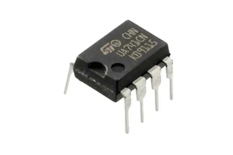
741 Integrated Circuit
The 741 integrated circuit (IC) is a widely used operational amplifier (op-amp) in the field of electronics. It is known for its versatility, ease of use, and reliability.
741 integrated circuit
The 741 integrated circuit (IC) is an iconic and versatile operational amplifier (op-amp) that has been a cornerstone in the field of electronics for decades. Known for its reliability, ease of use, and wide range of applications, the 741 op-amp remains an essential component for both beginners and seasoned engineers.
Integrator Circuit Using Op Amp 741
An integrator circuit is one of the fundamental analog signal processing circuits that uses an operational amplifier (op-amp). It produces an output that is proportional to the integral of its input signal.
The 741 op-amp is commonly used in such circuits due to its ease of use and reliability. Here’s a detailed description of how to build and understand an integrator circuit using the 741 op-amp.
741 Integrated Circuit FAQs
What is 741 Integrated Circuit?
The 741 IC is a widely-used operational amplifier (op-amp) known for its versatility and reliability in various electronic applications. It is often used in analog circuits for amplification, filtering, and signal processing.
What are the key features of the 741 op-amp?
- Supply Voltage: Typically ±15V, with a range from ±5V to ±18V.
- Input Offset Voltage: Typically 2mV.
- Input Bias Current: Typically 80nA.
- Gain-Bandwidth Product: 1 MHz.
- Slew Rate: 0.5V/µs.
- Output Voltage Swing: ±14V (with ±15V supply voltage).
What are the common applications of the 741 IC?
- Amplifiers: Inverting, non-inverting, differential, and voltage follower (buffer) amplifiers.
- Filters: Active filters such as low-pass, high-pass, band-pass, and band-stop filters.
- Oscillators: Wien bridge oscillators, square wave generators, and other signal generators.
- Analog Computation: Performing mathematical operations like addition, subtraction, integration, and differentiation.
- Voltage Comparators: Comparing voltage levels for various detection tasks.
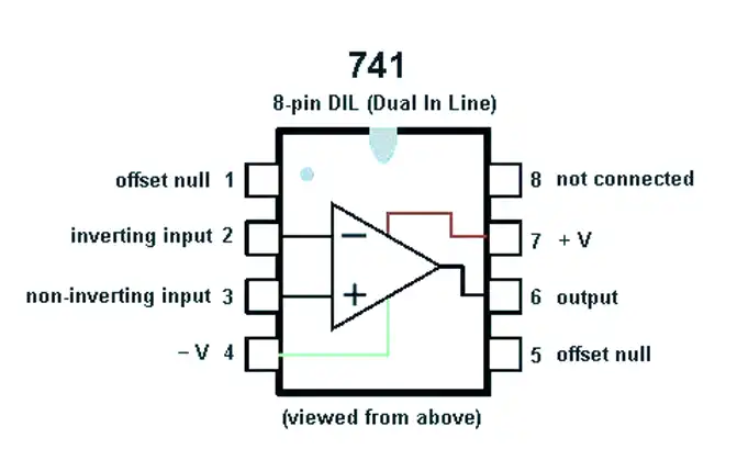
How do you connect a 741 op-amp?
- Pin 1: Offset Null
- Pin 2: Inverting Input (V-)
- Pin 3: Non-inverting Input (V+)
- Pin 4: Negative Power Supply (V-)
- Pin 5: Offset Null
- Pin 6: Output (Vout)
- Pin 7: Positive Power Supply (V+)
- Pin 8: Not Connected (NC)
What are the advantages of using the 741 IC?
- Versatility: Suitable for a wide range of applications.
- Stability: Provides reliable performance under various conditions.
- Ease of Use: Simple pin configuration and robust design make it easy to implement in circuits.
- Educational Value: Widely used in teaching analog electronics principles.