555 Timer Integrated Circuit: Master Time in Your Projects
Tired of sourcing integrated circuits? Want to add precise timing and control to your projects? Look no further than the legendary 555 timer IC! This versatile chip is your gateway to a world of timing possibilities.
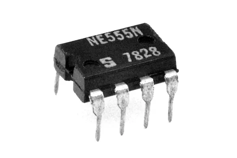
Timer Integrated Circuit
Don’t wait! Grab your 555 timer IC today and start building! You’ll be amazed at the creative timing applications you can unlock. We are the leading integrated circuit manufacturer to work out the best 555 timer integrated circuit solutions for your projects.
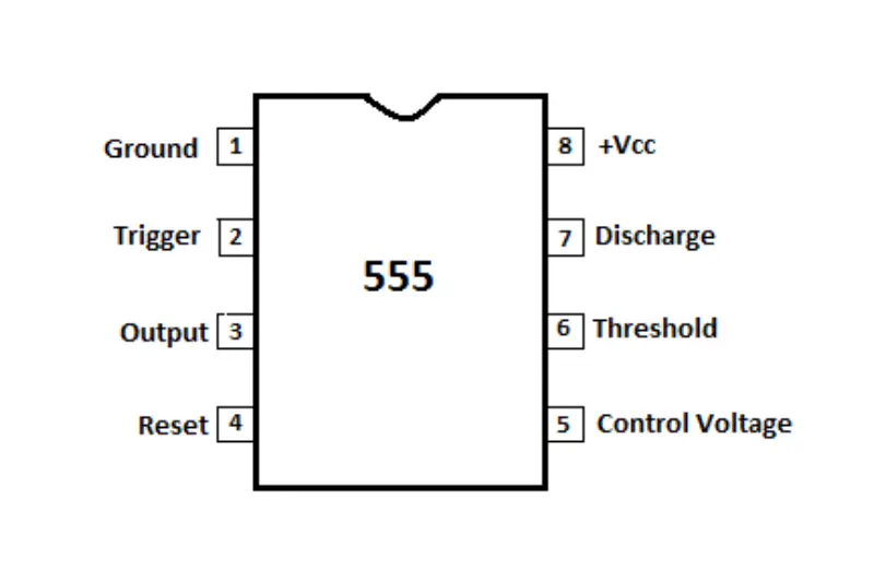
555 Timer Integrated Circuit Diagram
The 555 timer integrated circuit is a popular and versatile chip used for creating timers, oscillators, and pulse width modulation (PWM) circuits. It has three internal resistors and two comparators which allows it to function in various modes.
555 Timer Integrated Circuit Operation Modes
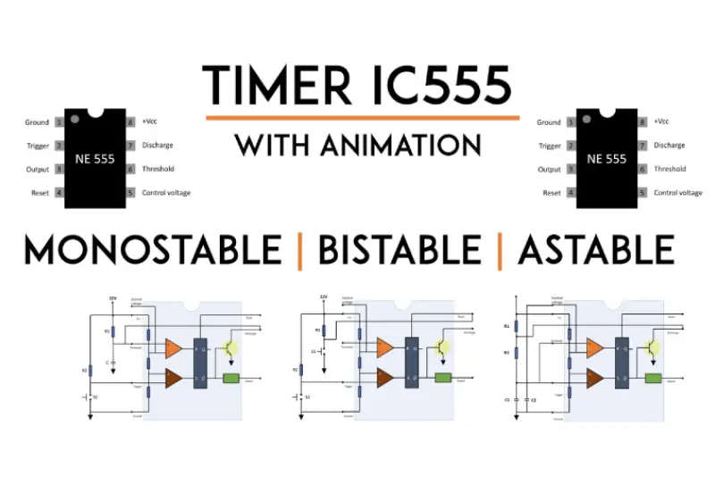
555 Timer Integrated Circuit Monostable Mode
The 555 timer’s monostable mode acts like a one-shot timer. A trigger signal starts a timer. Inside, a capacitor charges, slowly raising the voltage. Once it reaches a set point, the output flips high and stays that way for a timed duration based on the capacitor and resistor values. Finally, the capacitor discharges, resetting the timer and output for the next trigger.
555 Timer Integrated Circuit Bistable Mode
The 555 timer’s bistable mode acts like a flip-flop switch. One trigger pulse flips the output high, and another on a separate pin flips it low. It remembers its state (high or low) until triggered again. Think of it as a double-throw switch controlled by electronic pulses!
555 Timer Integrated Circuit Astable Mode
The 555 timer’s astable mode turns it into a free-running oscillator. Imagine a metronome. By connecting resistors and a capacitor, it generates a continuous stream of pulses at a set frequency. You control the pulse rate and how long each pulse lasts, making it perfect for blinking LEDs in patterns or creating audio tones.
555 Timer Integrated Circuit FAQs
what is 555 timer integrated circuit?
The 555 timer integrated circuit (IC) is a very popular and versatile chip commonly used in electronics projects that require timing functions. It’s known for its ease of use, affordability, and wide range of applications.
what can 555 timer integrated circuit do?
The 555 timer integrated circuit (IC) is a versatile workhorse in the world of electronics, particularly known for its ability to control time. Here are some of its key functionalities:
Timing Circuits: The 555 timer excels at creating precise time delays. You can set it to generate a single pulse after a specific duration (monostable mode) or create a continuous stream of pulses at a controlled rate (astable mode). This makes it perfect for applications like blinking LEDs, generating sound effects, or triggering actions in your circuits at specific intervals.
Oscillators: If you need a steady stream of electrical pulses at a particular frequency, the 555 timer can function as an oscillator. This comes in handy for driving LED patterns, creating audio tones, or providing clock signals for other circuits.
Pulse Width Modulation (PWM): This is a fancy way of saying the 555 timer can control the duty cycle of its output pulse. Duty cycle refers to the portion of a pulse that’s high compared to the total pulse period. By adjusting this, you can control the average voltage delivered over time. This is useful for dimming LEDs or varying the speed of a motor.
Think of it like this: Imagine the 555 timer as a faucet that controls the flow of time (voltage) in your circuit. You can set it to:
- Turn on the faucet for a specific duration (monostable mode).
- Turn on the faucet continuously, but control the water pressure (astable mode with adjustable duty cycle).
Beyond these core functionalities, the 555 timer also offers:
- Simplicity: It’s a relatively easy-to-use chip, requiring few external components to create functional circuits.
- Versatility: The three basic operating modes (monostable, astable, bistable) allow for a wide range of timing applications.
- ** affordability:** It’s an inexpensive component, making it accessible for hobbyists and beginners.
Due to these advantages, the 555 timer is a popular choice for:
- Hobbyists and Makers: Experiment with timing circuits and explore various functionalities without complex programming.
- Learning Electronics: A great tool for students to grasp timing concepts through hands-on projects.
- Prototyping Circuits: Rapidly build and test timing functions before integrating them into more sophisticated designs.
So, if your project involves precise timing, generating oscillations, or controlling power with PWM, the 555 timer IC might just be the perfect timekeeper for you!
555 timer integrated circuit working principle
The 555 timer IC works like a tiny maestro of time, controlling the flow of voltage in your circuit based on pre-set durations or continuous patterns.
Internal Components:
- Resistors: Three internally connected resistors with equal values act as a voltage divider, providing stable reference voltages for the circuit.
- Comparators: Two comparators constantly compare the voltage on a capacitor (connected to a specific pin) with these reference voltages.
- RS Flip-Flop: This internal switch controls the output state (high or low voltage).
- Discharge Transistor: This transistor acts as a gatekeeper, discharging the capacitor when needed.
The Maestro in Action (Modes):
The 555 timer operates in three main modes, each with a distinct way of controlling the output voltage:
Monostable Mode (One-Shot Timer): Imagine a kitchen timer.
A trigger signal kicks things off, forcing the output high.
The capacitor starts charging through a resistor, and comparator 1 monitors the voltage on the capacitor.
Once the capacitor voltage reaches a certain level (determined by the resistors and capacitor values), comparator 1 flips the RS flip-flop, causing the output to go low.
The discharge transistor activates, rapidly draining the capacitor.
Comparator 2 waits for the capacitor voltage to drop to a lower threshold.
When that happens, comparator 2 resets the flip-flop, and the circuit is ready for the next trigger.
Astable Mode (Oscillator): Think of a metronome keeping a steady beat.
No trigger is needed here. The capacitor charges and discharges repeatedly, creating a continuous stream of rectangular pulses at the output.
The resistors and capacitor determine the frequency (pulse rate) and duty cycle (ratio of pulse width to total pulse period) of the output.
Bistable Mode (Less Common): Imagine a simple light switch.
In this mode, the 555 timer acts like a basic flip-flop.
A momentary high pulse on the set pin triggers the output high.
A similar pulse on the reset pin flips the output low.
The output remains in that state until triggered again.
External Components:
While the 555 timer has these functionalities built-in, you’ll typically need external resistors and capacitors to set the specific timing characteristics (delays, frequencies, etc.) for your project. These components work in conjunction with the internal resistors and the capacitor charging/discharging cycles to control the timing behavior.
Applications:
The 555 timer’s versatility makes it a popular choice for various projects:
- Blinking LEDs with different patterns
- Creating sound effects
- Controlling motor speeds with PWM
- Generating timed delays for triggering actions
- Building simple oscillators
By understanding the internal workings and different modes, you can harness the power of the 555 timer to add precise timing control to your electronic creations!